
Computer Hardware Installation Guide

686 NT8D14 Universal Tr unk card
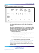
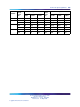
In Option 11C systems, the insertion loss from IPE ports to IPE ports is as
follows.
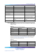
Table 246
Insertion Loss from IPE Ports to IPE Ports (measured in dB)
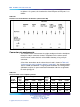
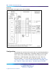
Connector pin assignments
The universal trunk card connects the eight analog trunks to the backplane
through a 160-pin connector shroud. Telephone trunks connect to the
universal trunk card at the back of the Media Gateway using a 25-pin
connector.
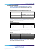
A list of the connections to the universal trunk card is shown in Table 247
"Universal trunk card - backplane pinouts" (page 686). See Communication
Server 1000M and Meridian 1 Large System Installation and Configuration
(NN43021-310) for I/O panel connector information and wire assignments
for each tip/ring pair.
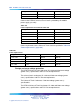
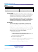
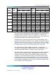
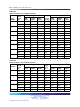
Table 247
Universal trunk card - backplane pinouts
Signal Signal
Trunk
Number
Back-
plane
Pin
RAN
mode
Paging
mode
Other
modes
Back-
plane
Pin
RAN
mode
Paging
mode
Other
modes
0
12A Tip Tip Tip 12B Ring Ring Ring
13A CP A N/A 13B MB RG N/A
1
14A Tip Tip Tip 14B Ring Ring Ring
15A CP A N/A 15B MB RG N/A
Nortel Communication Server 1000
Circuit Card Reference
NN43001-311 01.04 Standard
Release 5.0 23 May 2008
Copyright © 2003-2008, Nortel Networks
.