
Computer Hardware Installation Guide

678 NT8D14 Universal Tr unk card
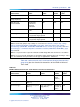
Trunk Types
Characteristic CO / FX / WATS DID / TIE
RAN Paging
Line leakage ˇ
S 30k ohms,
tip-to-ring,
tip-to-ground,
ring-to-ground
ˇ
S 30k ohms,
tip-to-ring,
tip-to-ground,
ring-to-ground
N/A N/A
AC induction rejection 10 V rms,
tip-to-ring,
tip-to-ground,
ring-to-ground
10 V rms,
tip-to-ring,
tip-to-ground,
ring-to-ground
N/A N/A
Note 1: Selected in software.
Note 2: Selected by jumper strap settings on card. Refer to Table 250 "Jumper strap settings -
factory standard (NT8D14BA, NT8D14BB)" (page 691), Table 251 "Jumper strap settings - extended
range (NT8D14BA, NT8D14BB, NT8D14BB)" (page 692), and Table 252 "Trunk types - termination
impedance and balance network (NT8D14BA, NT8D14BB)" (page 692) for details.
Note 3: For loop extender application, the maximum voltage applied between tip and ring is –105 V
±5%. The minimum dc loop resistance for this type of application is 1800 ohms.
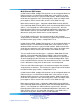
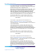
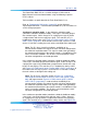
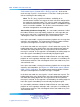
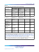
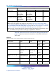
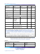
Table 234 "Universal trunk card - trunk interface electrical characteristics"
(page 678) gives the electrical characteristics of the NT8D14 Universal
Tr unk card.
Table 234
Universal trunk card - trunk interface electrical characteristics
Characteristic
CO/FX/WATS
trunks
DID or TIE
trunks
RAN
trunks
Paging
trunks
Terminal impedance 600 or 900 ohms (Note 1) 600/900
ohms
(Note 1)
600
ohms
Balance impedance 600 or 900 ohms (Note 1),
3COM, or 3CM2 (Note 2)
N/A N/A
Supervision type Ground or
loop start
(Note 3)
Loop start
(with ans sup)
(Note 3)
Contin
uous,
level, or
pulse
N/A
DC signaling loop length
(max)
1700-ohm loop with
near-end battery of
–42.75 V
2450-ohm loop
with near-end
battery of –44 V
600/90
0-ohm
loop
600 ohm loop
Far-end battery –42 to –52.5 V (Note
4)
–42 to –52.5 V
–42 to
–52 V
N/A
Minimum detected loop
current
20 mA 10 mA 10 mA N/A
Nortel Communication Server 1000
Circuit Card Reference
NN43001-311 01.04 Standard
Release 5.0 23 May 2008
Copyright © 2003-2008, Nortel Networks
.