
Computer Hardware Installation Guide

Engineering guidelines 399
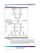
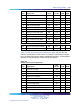
Pin Signal name
EIA
circuit
CCITT
circuit DTE DCE
2
Transmit Data (TX) BA
103
X
3
Receive Data (RX) BB
104
X
4
Request to Send (RTS) CA
105
X
5
Clear to Send (CTS) CB
106
X
6
Data Set Ready (DSR) CC
107
X
7
Signal Ground (SG) AB
102
——
8
Carrier Detect (CD) CF
109
X
15
Serial Clock Transmit (SCT) DB
114
X
17
Serial Clock Receive (SCR) DD
115
X
18
Local Loopback (LL) LL
141
X
20
Data Terminal Ready (DTR) CD
108.2
X
21
Remote Loopback (RL) RL
140
X
23
Data Rate Selector (DRS) CH/CI 111/112 X
24
External Transmit Clock (ETC) DA
113
X
25
Test Mode (TM) TM
142
X
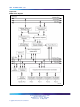
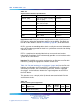
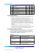
Table 173 "RS-422 interface pin assignments" (page 399) lists RS-422
interface specifications for EIA circuits. It shows the connector pin number,
the associated signal name, and the supported circuit type. It also indicates
whether the signal originates at the DTE or DCE device.
Table 173
RS-422 interface pin assignments
Pin Signal Name
EIA
Circuit DTE DCE
1
Frame Ground (FG) AA
——
2
Transmit Data (TXa) BAa X
3
Receive Data (RXa) BBa X
4
Request to Send (RTS) CA X
5
Clear to Send (CTS) CB X
7
Signal Ground (SG) AB
——
8
Receive Ready (RR) CF X
12
Receive Signal Timing (RST) DDb X
13
Transmit Data (TXb) BAb X
14
Transmit Signal Timing (TSTb) DBb X
Nortel Communication Server 1000
Circuit Card Reference
NN43001-311 01.04 Standard
Release 5.0 23 May 2008
Copyright © 2003-2008, Nortel Networks
.