
Computer Hardware Installation Guide

Functional description 343
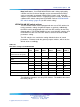
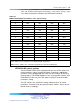
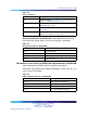
Table 144
Impedance level and loop mode switch settings
Swit
ch
Description
S9/S15 Switch Setting
1
Impedance level
OFF - 120 ohm
ON - 75 ohm
2
Spare X
3
Spare X
4
Unit mode OFF - Loop operates in the DTI2 mode
ON - Loop operates in the PRI2 mode
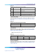
Transmission mode
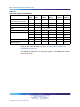
A per-trunk switch (S4/S10) provides selection of the digital trunk interface
type. Refer to Table 145 "Impedance level and loop mode switch settings"
(page 343).
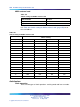
Table 145
Impedance level and loop mode switch settings
Description
S4/S10 switch settings
E1 OFF
Not used
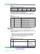
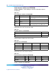
Line build out
A per-trunk set of three switches (S5/S11, S6/S12 and S7/S13) provides
the dB value for the line build out. Refer to Table 146 "Trunk interface line
build out switch settings" (page 343).
Note: Do not change this setup.
Table 146
Trunk interface line build out switch settings
Switch setting
Description S5/S11 S6/S12 S7/S13
0dB OFF OFF OFF
Receiver impedance
A per-trunk set of four DIP switches (S8/S14 provides selection between 75
or 120 ohm values. Refer to Table 147 "Trunk interface impedance switch
settings" (page 344).
Nortel Communication Server 1000
Circuit Card Reference
NN43001-311 01.04 Standard
Release 5.0 23 May 2008
Copyright © 2003-2008, Nortel Networks
.