
Computer Hardware Installation Guide

Installation and Configuration 277
Daisy-Chaining to MMI
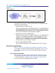
If two or more LEIs are installed and the MMI used, daisy-chain the cards
together to use one MMI terminal or modem. Make the selection for this dip
switch position based on how many LEIs are being installed.
MMI Master or Slave
This setting is used only if daisy-chaining the cards to the MMI terminal or
modem. It determines whether this card is a master or a slave in the daisy
chain. Select the master setting if there are no LEIs between this card and
the MMI terminal or modem. Select the slave setting if there are other cards
in the daisy chain between this card and the MMI.
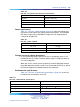
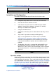
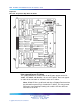
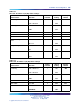
Table 115 "LEI card - Switch 1 dip switch settings" (page 277) through Table
117 "LEI card - XPEC address dip switch settings (Switch S1, positions
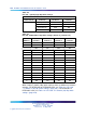
3-6)" (page 278) show the dip switch settings for Switch 1. Table 118 "LEI
card - E1 Switch 2 (S2) dip switch settings" (page 279) shows the dip switch
settings for Switch 2.
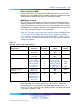
Table 115
LEI card - Switch 1 dip switch settings
Characteristic Selection
Switch
Position
Switch
Setting
Factory
Default
MMI port speed selection 1200 baud
2400 baud
1
1
ON
OFF
OFF
E1 signaling Ground start
Loop start
2
2
ON
OFF
OFF
IPE Shelf address for LEI Table 117 "LEI
card - XPEC
address dip switch
settings (Switch
S1, positions 3-6)"
(page 278)
3
4
5
6
Table 117 "LEI
card - XPEC
address dip switch
settings (Switch
S1, positions 3-6)"
(page 278)
OFF
OFF
OFF
OFF
Card type for ringer
allocation
XTI = 19
XMLC = 18
7
7
ON
OFF
OFF
E1 signaling See Table 116
"LEI card -
signaling-type dip
switch settings"
(page 278)
8
OFF OFF
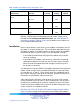
When dip switch #1, positions 2 and 8 are set to "Table," AB Bits are
configured by the user through the Set Mode MMI command (see "Set
Mode" (page 302)). Otherwise, the signaling scheme selected by dip switch
1, positions 2 and 8 are used.
Nortel Communication Server 1000
Circuit Card Reference
NN43001-311 01.04 Standard
Release 5.0 23 May 2008
Copyright © 2003-2008, Nortel Networks
.