
Computer Hardware Installation Guide

220 NT5D11 and NT5D14 Lineside T1 Interface cards
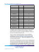
Item TN
T1 Channel Number
Motherboard
5
6
Motherboard
6
7
Motherboard
7
8
Motherboard
89
Motherboard
910
Motherboard
10 11
Motherboard
11 12
Motherboard
12 13
Motherboard
13 14
Motherboard
14 15
Motherboard
15 16
Daughterboard
017
Daughterboard
118
Daughterboard
219
Daughterboard
320
Daughterboard
421
Daughterboard
5
22
Daughterboard
623
Daughterboard
7
24
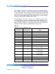
Although much of the architecture and many of the features of the Lineside
T1 card differ from the analog line card, the Lineside T1 card has been
designed to emulate an analog line card to the Meridian 1 software.
Because of this, the Lineside T1 card software configuration is performed
the same as two adjacent analog line cards.
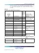
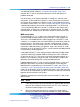
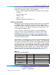
All 24 T1 channels carried by the Lineside T1 card are individually
configured using the Analog (500/2500-type) Telephone Administration
program LD 10. Use Table 102 "DX-30 to T1 time slot mapping" (page
221) to determine the correct unit number and the technical document
Software Input/Output Reference — Administration (NN43001-611) for LD
10 service change instructions.
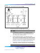
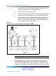
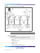
The Lineside T1 card circuitry routes 16 units (0-15) on the motherboard and
eight (0-7) units on the daughterboard to 24 T1 channels. The motherboard
circuit card is located in the left card slot, and the daughterboard circuit card
is located in right card slot. For example, if the Lineside T1 card is installed
into card slots 0 and 1, the motherboard would reside in card slot 0 and the
daughterboard would reside in card slot 1. In order to configure the terminal
Nortel Communication Server 1000
Circuit Card Reference
NN43001-311 01.04 Standard
Release 5.0 23 May 2008
Copyright © 2003-2008, Nortel Networks
.