
Computer Hardware Installation Guide

Installation and configuration 197
MMI Master or Slave
This setting is used only if daisy-chaining the cards to the MMI terminal or
modem. This setting determines whether this card is a master or a slave in
the MMI daisy-chain. Select the master setting if this card is the card that is
cabled directly into the MMI terminal or modem; select the slave setting if
this card is cabled to another Lineside T1 card in a daisy chain.
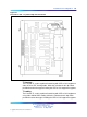
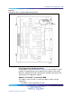
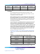
Table 91 "Lineside T1 card-T1 Switch 1 (S1) dip switch settings" (page
197) through Table 94 "Lineside T1 card - CPE or CSU distance dip switch
settings (Switch S2, positions 3 - 5)" (page 198) describe the proper dip
switch settings for each type of T1 link. After the card has been installed, the
MMI displays the DIP switch settings the command Display Configuration
is used. See "Functional description" (page 391) for details on how to
invoke this command.
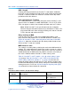
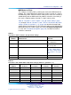
Table 91
Lineside T1 card-T1 Switch 1 (S1) dip switch settings
Dip Switch
Number Characteristic Selection
1
MMI port speed selection On = 1200 baud
Off = 2400 baud
2
T1 signaling On = Ground start
Off = Loop start
3–6
XPEC Address for the Lineside T1 card See Table 92 "Lineside
T1 card - XPEC address
dip switch settings (Switch
S1, positions 3 - 6)" (page
197).
7
Not Used Leave Off
8
Reserved for SL-100 use Leave Off
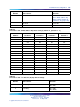
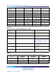
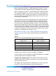
Table 92
Lineside T1 card - XPEC address dip switch settings (Switch S1, positions 3 - 6)
XPEC
Address
S1 Switch
Position 3
S1 Switch
Position 4
S1 Switch
Position 5
S1 Switch
Position 6
00
Off Off Off Off
01
Off Off Off On
02
Off Off On Off
03
Off Off On On
04
Off On Off Off
05
Off On Off On
06
Off On On Off
Nortel Communication Server 1000
Circuit Card Reference
NN43001-311 01.04 Standard
Release 5.0 23 May 2008
Copyright © 2003-2008, Nortel Networks
.