
Computer Hardware Installation Guide

194 NT5D11 and NT5D14 Lineside T1 Interface cards
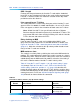
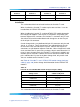
Dip Switch
Number Characteristic Selection
3–5
CPE or CSU distance See Table 90 "Lineside T1 card -
CPE or CSU distance dip switch
settings (Switch S2, positions 3
- 5)" (page 194)
6
Line processing on T1 link failure On = On-hook
Off = Off-hook
7
Daisy-chaining to MMI On = Yes
Off = No
8
MMI Master or Slave On = Master
Off = Slave
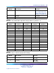
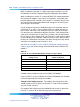
Table 90
Lineside T1 card - CPE or CSU distance dip switch settings (Switch S2, positions 3 - 5)
Distance
S2 Switch
Position 3
S2 Switch
Position 4
S2 Switch
Position 5
0–133
On Off Off
134–266
Off On On
267–399
Off On Off
400–533
Off Off On
534–655
Off Off Off
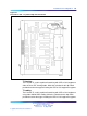
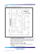
Begin the installation and configuration of the Lineside T1 card by selecting
the proper dip switch settings for the environment. The Lineside T1 card
contains two dip switches, each containing eight switch positions. They are
located in the upper right corner of the motherboard circuit card as shown
in Figure 33 "Lineside T1 card - T1 protocol dip switch locations" (page
195). The settings for these switches are shown in Table 91 "Lineside T1
card-T1 Switch 1 (S1) dip switch settings" (page 197) through Table 94
"Lineside T1 card - CPE or CSU distance dip switch settings (Switch S2,
positions 3 - 5)" (page 198).
When the Lineside T1 card is oriented as shown in Figure 33 "Lineside T1
card - T1 protocol dip switch locations" (page 195), the dip switches are ON
when they are up, and OFF when they are down. The dip switch settings
configure the card for the following parameters:
MMI port speed selection
This dip switch setting selects the appropriate baud rate for the terminal or
modem (if any) that is connected to the MMI.
Nortel Communication Server 1000
Circuit Card Reference
NN43001-311 01.04 Standard
Release 5.0 23 May 2008
Copyright © 2003-2008, Nortel Networks
.