
Computer Hardware Installation Guide

186 NT5D11 and NT5D14 Lineside T1 Interface cards
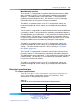
Characteristics
Description
Signaling Loop or ground start A/B robbed-bit
Distance to Customer Premise
Equipment (CPE) or Channel Service
Unit
0-199.6 meters (0–655 feet)
Table 81 "Lineside T1 card - line interface unit electrical characteristics"
(page 186) provides a technical summary of the T1 line interfaces, and
Table 83 "Lineside T1 card - power required" (page 187) lists the maximum
power consumed by the card.
T1 channel specifications
Table 81 "Lineside T1 card - line interface unit electrical characteristics"
(page 186) provides specifications for the 24 T1channels. Each
characteristic is set by dip switches. See "Installation and configuration"
(page 188) for the corresponding dip switch settings.
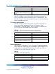
Table 81
Lineside T1 card - line interface unit electrical characteristics
Characteristics
Description
Framing ESF or D4
Coding AMI or B8ZS
Signaling Loop or ground start A/B robbed-bit
Distance to Customer Premise
Equipment (CPE) or Channel Service
Unit
0-199.6 meters (0–655 feet)
Power requirements
The Lineside T1 card requires +15 V, –15 V, and +5 V from the backplane.
One NT8D06 IPE Power Supply AC or NT6D40 IPE Power Supply DC can
supply power to a maximum of eight Lineside T1 cards. See Table 82
"Lineside T1 card - power required" (page 186).
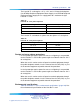
Table 82
Lineside T1 card - power required
Voltage
Current (max.)
+ 5.0 V dc 1.6 Amp
+15.0 V dc 150 mA.
–15.0 V dc 150 mA.
Nortel Communication Server 1000
Circuit Card Reference
NN43001-311 01.04 Standard
Release 5.0 23 May 2008
Copyright © 2003-2008, Nortel Networks
.