
Computer Hardware Installation Guide

QPC775 Clock Controller card 115
QPC720 Primary Rate Interface card
Table 56
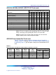
QPC720 Primary Rate Interface card
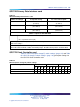
Switch S2 settings
To repeater facility To cross-connect point
5on
0–45 m
(0–150 ft)
0–30 m
(0–100 ft)
2, 4, 6 on 46–135 m
(151–450 ft)
31–100 m
(101–355 ft)
1, 3, 7 on 136–225 m
(451–750 ft)
101–200 m
(356–655 ft)
Switch 3 option for DTI with ESF
SW3-1 on = extended superframe format (ESF)
off = superframe format (SF)
Note: All positions on S2 (location B22) are OFF except as shown under the column labeled
"Switch S2 settings."
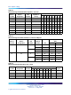
Note: Framing format, line encoding, and method of yellow alarm are selectable for both DTI and
PRI in LD17 with the DLOP, LCMT, and YALM prompts. All SW3 switch positions should be OFF.
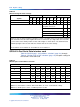
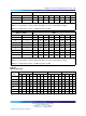
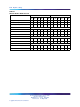
QPC775 Clock Controller card
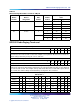
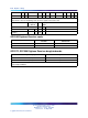
Table 57 "QPC775 (before vintage E) switch settings" (page 115) and Table
58 "QPC775 vintage E switch settings" (page 116) give option settings for
the QPC775 Clock Controller card.
Table 57
QPC775 (before vintage E) switch settings
SW2 SW3 SW4
System
123412341234
CS 1000M MG off off off off off off off off
on on on on
CS 1000M SG
on on on on
off off off off
on on on on
Nortel Communication Server 1000
Circuit Card Reference
NN43001-311 01.04 Standard
Release 5.0 23 May 2008
Copyright © 2003-2008, Nortel Networks
.