
Computer Hardware Installation Guide
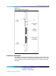
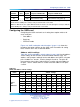

1110 QPC841 Quad Serial Data Interface card
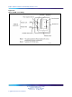
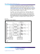
SW14
Port 1 Port 2
Switch settings
SW15
Port 3 Port 4 1 2 3 4
5
6
7
8
14 15
off off off off off off off off
Note 1: On SW16, positions 1, 2, 3, and 4 must be OFF.
Note 2: To avoid address conflicts, SW14 and SW15 can never use identical settings.
Note 3: To disable ports 1 and 2, set SW14 position 1 to ON. To disable ports 3 and 4, set SW15
position 1 to ON.
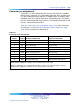
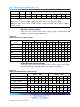
Baud rate switch settings
Table 454 "QSDI card baud rate switch settings" (page 1110) lists the switch
settings necessary to set the baud rate.
Table 454
QSDI card baud rate switch settings
Port 1 – SW10 Port 2 – SW11 Port 3 – SW12 Port 4 – SW13
Baud
rate
1234123412341234
150
off off
on on
off off
on on
off off
on on
off off
on on
300
off
on
off
on
off
on
off
on
off
on
off
on
off
on
off
on
600
off off off
on
off off off
on
off off off
on
off off off
on
1200
off
on on
off off
on on
off off
on on
off off
on on
off
2400
off off
on
off off off
on
off off off
on
off off off
on
off
4800
off
on
off off off
on
off off off
on
off off off
on
off off
9600
off off off off off off off off off off off off off off off off
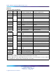
DTE/DCE mode switch settings
Table 455 "QSDI card DTE/DCE mode switch settings" (page 1110) shows
the DTE/DCE mode selection switches for the four serial ports.
Table 455
QSDI card DTE/DCE mode switch settings
Port 1 – SW8 Port1 – SW9
Mode 1234
5
61234
5
6
DTE (Terminal)
on on on on on on
off off off off off off
DCE (Modem) off off off off off off
on on on on on on
Port 2 – SW6 Port 2 – SW7
Mode 1234
5
61234
5
6
DTE (Terminal)
on on on on on on
off off off off off off
DCE (Modem) off off off off off off
on on on on on on
Nortel Communication Server 1000
Circuit Card Reference
NN43001-311 01.04 Standard
Release 5.0 23 May 2008
Copyright © 2003-2008, Nortel Networks
.