
Computer Hardware Installation Guide

Configuring the QSDI card 1109
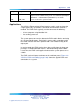
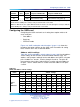
Pin
Number Port Signal Purpose in DTE mode Purpose in DCE mode
21
CD Carrier detect (Note 1 Carrier detect (not used)
22
DTR Data terminal ready Data terminal ready (Note 2))
Note 1: In DTE mode, the signals CD, DSR, and CTS are tied to +12 volts (through a resistor) to
indicate that the QSDI port is always ready to transmit and receive data.
Note 2: In DCE mode, the signals DTR and RTS are tied to +12 volts (through a resistor) to indicate
that the QSDI port is always ready to transmit and receive data.
Configuring the QSDI card
Configuring the QSDI card consists of setting these option switches for
each serial port:
•
Port address
•
Baud rate
•
DTE/DCE mode
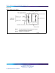
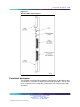
Figure 316 "QSDI card option switch locations" (page 1112) shows the
location of the option switches on the QSDI card. Instructions for setting
these switches are in the section that follows.
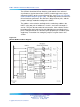
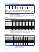
Address switch settings
Table 453 "QSDI card address switch settings" (page 1109) lists the address
switch settings for the QPC841 Quad Serial Data Interface card. The
address select jumpers and logic on the card address the UARTs using two
pairs of addresses: 0 and 1, 2 and 3, through 15 and 16. The pairs do
not need to be consecutive. Switch SW14 is used to select the addresses
for ports 1 and 2. Switch SW15 is used to select the addresses for ports
3 and 4.
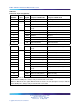
Table 453
QSDI card address switch settings
SW14
Port 1 Port 2
Switch settings
SW15
Port 3 Port 4 1 2 3 4
5
6
7
8
01
off off off off off
on on on
23
off off off off off
on on
off
4
5
off off off off off
on
off
on
6
7
off off off off off
on
off off
89
off off off off off off
on on
10 11
off off off off off off
on
off
12 13
off off off off off off off
on
Device
pair
addresses
Nortel Communication Server 1000
Circuit Card Reference
NN43001-311 01.04 Standard
Release 5.0 23 May 2008
Copyright © 2003-2008, Nortel Networks
.