
Computer Hardware Installation Guide


LED indicators 1043
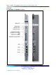
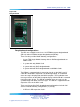
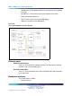
Faceplate buttons
Reset
Reset (RST) generates a hard reset of the card.
Init
Init (INI) generates a manual initialization of the software.
DIP switch
The DIP switch selects the media drive. CF MASTER/POSITION1 selects
the Compact Flash (CF) FMD and HD MASTER/POSITION2 selects the
Hard Drive FMD.
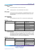
LED indicators
Status LED
The functionality of the Status LED is summarized in the following table.
Table 428
Status LED functionality
LED
Color CP PM Status
Status Green After sysload
Flashing Green Not implemented
Yellow Not implemented
Orange Selftest error
Red During sysload phase 2
Flashing Red During sysload phase 1
Off No power
Active CPU LED
The CP PM can operate in single CPU mode or dual CPU mode. A tri-color
LED indicates the Call Server redundancy status. This LED is not used by
the Signaling Server and is OFF if it is a Signaling Server. The functionality
of the active CPU LED is summarized in the following table.
Table 429
Call server redundancy status
LED
Color Status
Call server redundancy Green Redundant mode, active
Yellow Redundant mode, standby
Red Redundant mode, fault (HSP
down)
Off Standard mode
Nortel Communication Server 1000
Circuit Card Reference
NN43001-311 01.04 Standard
Release 5.0 23 May 2008
Copyright © 2003-2008, Nortel Networks
.