
Telephone System Installation and Maintenance Guide
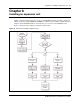


Chapter 8 Installing an expansion unit 93
BCM50 Installation and Maintenance Guide
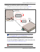
Verifying the media bay module switch settings
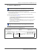
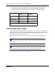
Each MBM has dip switches on the back or underside of the module (see Figure 40).
Figure 40 Switches on the media bay module (not applicable for GASM or GATM)
Verify that the dip switches for your MBMs are in the default factory positions as follows:
If you are installing a DTM, BRIM, 4x16, DSM16, DSM32, or ASM8, ensure that all the switches
are on. This is the default setting for the MBM switches. After you have set the switches, proceed
to “Installing a media bay module in an expansion unit” on page 95.
Note: The GASM and GATM MBMs have a different dip switch configuration
than shown in Figure 40. Refer to “To set GASM dip switches” on page 94 and
“To set GATM dip switches” on page 94 for more information.
Caution: The MBM dip switches must remain in their default factory position.
Any required modifications to the MBM settings are made through the software.
654 3 21
Off
On
Underside of the
media bay module
dip switches
Back of the media bay module
123456
On
Off
Rear view of the media bay module
Module is
right-side up