
Telephone System Installation and Maintenance Guide


Chapter 2 Introducing the BCM50 hardware 53
BCM50 Installation and Maintenance Guide
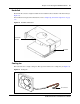
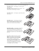
Router card
The BCM50e main unit has a router card that uses an Ethernet interface to connect to a WAN edge
device (for example, an external ADSL modem or cable modem).
The BCM50a main unit has a router card that uses an ADSL interface to connect the BCM50
system to the Internet Service Provider (ISP).
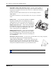
For information about replacing the router card, refer to “Replacing an internal component” on
page 189.
Field-replaceable units
Table 6 and Table 7 on page 54 provide a list of field-replaceable units (FRU) and media bay
modules (MBM) for the BCM50 system. Use these tables as references when you need to order,
replace, or install hardware components. The tables provide references to the component
descriptions and installation procedures.
Note: The analog trunk interfaces and analog telephony device interfaces on the RJ-21
telephony connector are compatible with the North American telephony interface
standards only.
If your BCM50 system is in a country that uses a different telephony standard, you must
use media bay modules for your analog trunks and media bay modules or ATAs for your
analog telephony devices.
Note: The product engineering code (PEC) can change over time; consult the
catalog for the latest information.
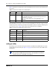
Table 6 Field-replaceable units
Component description FRU Description Replacement procedure
Router card with Ethernet connector “Router card” “Replacing an internal component”
Router card with ADSL interface “Router card” “Replacing an internal component”
Hard disk, programmed “Hard disk” “Replacing an internal component”
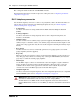
Power supply “Power supply” “Replacing a power supply”
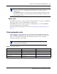
Cooling fan “Cooling fan” “Replacing an internal component”