
Telephone System Installation and Maintenance Guide


38 Chapter 2 Introducing the BCM50 hardware
N0027152 01N0027152 01
Expansion unit and media bay modules
In addition to a main unit, the BCM50 system can have up to two expansion units. An expansion
unit connects to the main unit and provides additional functionality. Refer to Figure 4 and Table 2
for expansion unit port locations and descriptions.
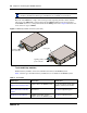
The expansion unit is designed to accommodate one media bay module (MBM) that enables you to
connect additional telephony equipment to the BCM50 system. The MBMs connect with external
devices to implement various types of voice trunks and stations. Refer to Table 3 on page 40 for a
list of trunk MBMs and Table 4 on page 42 for a list of station MBMs that can be used with your
BCM50 system. Refer also to Table 7 on page 54 for a complete list of MBMs with links to
additional information.
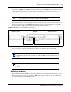
Ensure that the MBM dip switches are set correctly (see “Verifying the media bay module switch
settings” on page 93).
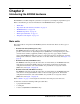
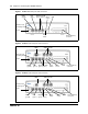
Figure 4 Expansion unit connections
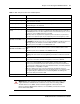
Table 2 Expansion unit ports/connectors and descriptions
Port/connector Description
LAN port (port 1) An RJ-45 jack used to connect the customer LAN to the main unit.
The LAN port on the expansion unit is connected to the internal Ethernet switch on
the main unit. You can use the expansion unit LAN port to connect an additional
device to the LAN.
Power connector A barrel connector jack used to connect the power supply to the expansion unit.
Retention clip mounting hole A small hole into which you insert the retention clip. The retention clip secures the
power connector to the unit.
Expansion port An RJ-45 jack used to connect the expansion unit to the main unit.
Ejector The ejector is used to remove the media bay module from the expansion unit.
MBM bay A slot into which you install an MBM.
Ejector Expansion
port
Power
LAN port
MBM bay
Retention clip
mounting hole