
Telephone System Installation and Maintenance Guide


Chapter 2 Introducing the BCM50 hardware 37
BCM50 Installation and Maintenance Guide
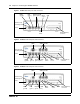
Table 1 Main unit ports/connectors and descriptions
Port/connector Description
Power connector A barrel connector jack used to connect the power supply to the main unit.
Retention clip mounting hole A small hole into which you insert the retention clip. The retention clip secures the
power connector to the unit.
OAM port (port 0) An RJ-45 jack used to connect a computer running administration software, such as
Element Manager, to the main unit.
LAN port (port 1) An RJ-45 jack used to connect the customer LAN to the main unit.
Expansion/LAN ports (ports 2
and 3)
Two RJ-45 jacks used to connect the expansion units to the main unit. The expansion
ports can also provide connections to the Ethernet switch internal to the main unit. If
the BCM50 system does not have expansion units connected to these ports, you can
use them to connect additional devices to the LAN.
Note: Keycodes are required for the expansion ports to function. If you purchase a
keycode for one expansion port only, the expansion port on the left (port 2) is active.
WAN port
(BCM50a and BCM50e only).
For BCM50a: An RJ-11 jack used to connect the BCM50a main unit to the ADSL line
provided by your Internet service provider (ISP).
For BCM50e: An RJ-45 jack you use to connect the BCM50e to the Ethernet port of a
WAN edge device (for example, an external ADSL modem or cable modem).
Note: This port is not available on the BCM50 main unit.
Additional LAN ports
(BCM50a and BCM50e only).
Three RJ-45 jacks that provide connections to the Ethernet switch in the BCM50a and
BCM50e main units. You can use these ports to connect additional devices to the
LAN.
Note: These ports are not available on the BCM50 main unit.
reset switch A button to activate the reset feature. Use a long thin tool to press the button.
Warning: The reset feature erases programming information and must be used with
care.
Music source port A phono jack used to connect a music source to the main unit. If you use this port, the
music source connections on the RJ-21 telephony connector are disabled.
USB port A USB 1.1-compatible port used to connect a USB storage device or the data
interface for an uninterruptable power supply (UPS) to the main unit. The data
interface for the UPS allows the main unit to monitor and control the UPS functions.
To connect both a USB storage device and UPS data interface, an industry-standard
USB hub (USB 1.1-compatible) is required.
Note: The USB storage device must be formatted for the FAT32 file system. If
necessary, reformat the USB storage device by plugging it into your computer’s USB
port, right-clicking the USB device icon, and selecting FAT32 reformatting. This
destroys any data you had on the USB.
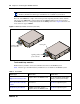
RJ-21 telephony connector An RJ-21 port used to connect telephony devices to the main unit.
Warning: External equipment connected to the auxiliary ringer, page relay, page
output, and music-on-hold interfaces must use safety extra low voltage (SELV).
All four interfaces are SELV, and the external equipment connected to these
interfaces must be SELV. If these interfaces are not SELV, you must use external
line isolation units (LIU).