
Telephone System Installation and Maintenance Guide


Appendix A RJ-21 telephony connector wiring chart 205
BCM50 Installation and Maintenance Guide
Appendix A
RJ-21 telephony connector wiring chart
You can connect 4 analog telephone lines, 4 analog telephony devices, and 12 digital telephones to
the RJ-21 telephony connector.
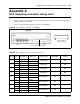
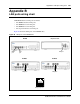
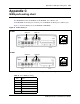
Figure 79 shows the RJ-21 telephony connector on a BCM50.
Figure 79 RJ-21 telephony connector on a BCM50
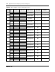
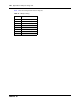
Table 34 lists the wiring details for the RJ-21 telephony connector.
Table 34 RJ-21 telephony connector wiring (Sheet 1 of 2)
Device Pin Connection Wire color Type of device Default DN
Default line
number
1
26 Tip White-Blue
Analog line — 061
1 Ring Blue-White
2
27 Tip White-Orange
Analog line — 062
2 Ring Orange-White
3
28 Tip White-Green
Analog line — 063
3 Ring Green-White
4
29 Tip White-Brown
Analog line — 064
4 Ring Brown-White
5
30 Tip White-Slate
Analog telephone 233 —
5 Ring Slate-White
6
31 Tip Red-Blue
Analog telephone 234 —
6 Ring Blue-Red
7
32 Tip Red-Orange
Analog telephone 235 —
7 Ring Orange-Red
8
33 Tip Red-Green
Analog telephone 236 —
8 Ring Green-Red
Main Unit
RJ-21 telephony connector
RJ-21 telephony
connector pin out