
BayStack User Guide

Using the BayStack 350 10/100/1000 Series Switch
1-4
304376-B Rev 00
All BayStack 350 switches are shipped with port connectors configured as MDI-X
(media-dependent interface-crossover). These ports connect over straight cables to
the network interface controller (NIC) card in a node or server, similar to a
conventional Ethernet repeater hub. If you are connecting to another Ethernet hub
or Ethernet switch, you need a crossover cable unless an MDI connection exists
on the associated port of the attached device (see “MDI and MDI-X Devices” on
page D-2).
The switches use autosensing ports that are designed to operate at 10 Mb/s or at
100 Mb/s, depending on the connecting device. These ports support the IEEE
802.3u autonegotiation standard, which means that when a port is connected to
another device that also supports the IEEE 802.3u standard, the two devices
negotiate the best speed and duplex mode of operation.
The switch ports also support half- and full-duplex mode operation (see
“Connecting the 10BASE-T/100BASE-TX Ports” on page 2-9).
The switch uses 10BASE-T/100BASE-TX RJ-45 port connectors to connect to
10 Mb/s or 100 Mb/s Ethernet segments or nodes.
See Appendix D, “Connectors and Pin Assignments” for more information about
the RJ-45 port connectors.
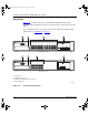
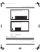
LED Display Panel
Figure 1-3
shows the LED display panels for the BayStack 350-24T and the
BayStack 350-12T models.
Refer to Table 1-1
for a description of the LEDs.
Note:
Use only Category 5 copper unshielded twisted pair (UTP) cable
connections when connecting 10BASE-T/100BASE-TX ports.
Note:
The LED display panel configuration for your switch may be different
than shown in Figure 1-3
, depending on the date of manufacturing (see the
note in “
10BASE-T/100BASE-TX Port Connectors” on page 1-3).
kombk.book Page 4 Thursday, February 18, 1999 10:59 AM