Part No.
Copyright © 2000 Nortel Networks All rights reserved. November 2000. The information in this document is subject to change without notice. The statements, configurations, technical data, and recommendations in this document are believed to be accurate and reliable, but are presented without express or implied warranty. Users must take full responsibility for their applications of any products specified in this document. The information in this document is proprietary to Nortel Networks NA Inc.
EC Declaration of Conformity This product conforms (or these products conform) to the provisions of Council Directive 89/336/EEC and 73/23/EEC.
Canada Requirements Only (continued) Repairs to certified equipment should be coordinated by a representative designated by the supplier. Any repairs or alterations made by the user to this equipment, or equipment malfunctions, may give the telecommunications company cause to request the user to disconnect the equipment.
FCC Part 68 Compliance Statement This equipment complies with Part 68 of FCC Rules. All direct connections to telephone network lines must be made using standard plugs and jacks compliant with FCC Part 68. Please note the following: 1. You are required to request service from the telephone company before you connect the unit to a network.
Nortel Networks NA Inc. Software License Agreement NOTICE: Please carefully read this license agreement before copying or using the accompanying software or installing the hardware unit with pre-enabled software (each of which is referred to as “Software” in this Agreement). BY COPYING OR USING THE SOFTWARE, YOU ACCEPT ALL OF THE TERMS AND CONDITIONS OF THIS LICENSE AGREEMENT. THE TERMS EXPRESSED IN THIS AGREEMENT ARE THE ONLY TERMS UNDER WHICH NORTEL NETWORKS WILL PERMIT YOU TO USE THE SOFTWARE.
for the security of its own data and information and for maintaining adequate procedures apart from the Software to reconstruct lost or altered files, data, or programs. 4. Limitation of liability.
Contents Preface Before You Begin ............................................................................................................xvii Text Conventions ........................................................................................................... xviii Acronyms .........................................................................................................................xix Hard-Copy Technical Manuals .......................................................................
Connecting a Management Console or Modem ...........................................................1-12 Connecting a Terminal Console .............................................................................1-12 Connecting a PC Console ......................................................................................1-14 Connecting a Modem .............................................................................................1-16 Connecting to the DC Power Source .............................
Chapter 3 Starting the AN/DC and ANH-8/DC About Software Installation .............................................................................................3-1 Boot Options ............................................................................................................3-2 Installing the Flash Memory Card ...................................................................................3-3 Using EZ Install ...................................................................................
Appendix B Using Local Boot (the Quick-Start Procedure) Filling Out the Quick-Start Worksheets ......................................................................... B-2 Global Information Worksheet ................................................................................. B-3 Router Protocol Worksheets ................................................................................... B-5 Wide Area Protocol Worksheets .............................................................................
Figures Figure 1-1. Mounting Hardware ..................................................................................1-2 Figure 1-2. Console Cables ........................................................................................1-3 Figure 1-3. Attaching Flange Brackets to the AN/DC .................................................1-7 Figure 1-4. Installing the AN/DC in a Rack .................................................................1-8 Figure 1-5. Mounting the AN/DC on a Wall ..
Figure 2-17. Connecting a PC Console to the ANH-8/DC ..........................................2-23 Figure 2-18. Connecting a Modem to the ANH-8/DC .................................................2-25 Figure 2-19. ANH-8/DC Power Switch and DC Terminals ..........................................2-26 Figure 2-20. Attaching the ANH-8/DC Power Input Cables ........................................2-27 Figure 2-21. Attaching the ANH-8/DC Earth Ground Cable .......................................2-28 Figure 3-1.
Tables Table 1-1. Console Parameters ..............................................................................1-13 Table 1-2. Modem Parameters ................................................................................1-16 Table 2-1. Console Parameters ..............................................................................2-20 Table 2-2. Modem Parameters ................................................................................2-24 Table 3-1.
xvi Table D-7. V.35 Interface (Order No. 7220) .............................................................. D-5 Table D-8. X.21 Interface (Order No. 7224) .............................................................. D-6 Table D-9. ISDN BRI Power Requirements .............................................................. D-7 Table D-10. ISDN BRI Clearances and Creepage Distances ..................................... D-9 Table D-11. ISDN BRI Safety Status (Order Nos.
Preface Read this guide for instructions on how to install, start, and operate Access Node or 8-Port Access Node Hub models that have a single DC input switching power supply, the AN™/DC and ANH™-8/DC.
Installing and Operating AN/DC and ANH-8/DC Systems Text Conventions This guide uses the following text conventions: angle brackets (< >) Indicate that you choose the text to enter based on the description inside the brackets. Do not type the brackets when entering the command. Example: If the command syntax is: ping , you enter: ping 192.32.10.12 bold text Indicates command names and options and text that you need to enter. Example: Enter show ip {alerts | routes}.
Preface screen text Indicates system output, for example, prompts and system messages. Example: Set Trap Monitor Filters vertical line ( | ) Separates choices for command keywords and arguments. Enter only one of the choices. Do not type the vertical line when entering the command. Example: If the command syntax is: show ip {alerts | routes}, you enter either: show ip alerts or show ip routes, but not both.
Installing and Operating AN/DC and ANH-8/DC Systems xx IEEE Institute of Electrical and Electronic Engineers IP Internet Protocol ISDN Integrated Services Digital Network ISO International Organization for Standardization ITU-T International Telecommunication Union –Telecommunication (formerly CCITT) LAN local area network LED light-emitting diode LMI Local Management Interface MAC media access control MAU media access unit MDI Medium-Dependent Interface MDI-X Medium-Dependent Inter
Preface Hard-Copy Technical Manuals You can print selected technical manuals and release notes free, directly from the Internet. Go to the support.baynetworks.com/library/tpubs/ URL. Find the product for which you need documentation. Then locate the specific category and model or version for your hardware or software product. Use Adobe Acrobat Reader to open the manuals and release notes, search for the sections you need, and print them on most standard printers. Go to Adobe Systems at www.adobe.
Chapter 1 Installing the AN/DC This chapter describes how to install the AN/DC. Danger: Due to high-energy hazards, only qualified service personnel are permitted to install the AN/DC. Topics in this chapter include • • • • • Preparing for Installation Installing the AN/DC (on a desktop, in a rack, or on the wall) Connecting Communications Cables Connecting a Management Console or Modem Connecting to the DC Power Source For information on how to install the ANH-8/DC, go to Chapter 2.
Installing and Operating AN/DC and ANH-8/DC Systems 1. Inspect all items for any shipping damage. Caution: In particular, check the AN/DC for any damage to the ports on the back panel. If you detect damage, do not install the AN/DC. Call your local Nortel Networks Technical Response Center. 2. Make sure that your shipping package contains the following items: • • • • • Mounting hardware (Figure 1-1). Console/modem cable kit (Figure 1-2). Any network cables ordered with the router.
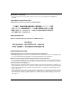
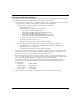
Installing the AN/DC DB-25 receptacle null nodem adapter DB-9 receptacle to DB-25 plug serial cable For connecting an optional terminal or modem to the console service port AN0002A Figure 1-2. Console Cables Supplying Tools and Equipment You may need items that are not part of the ANH-8/DC shipping accessories. Before installing the ANH-8/DC hardware, ensure that you have all the cables, tools, and other equipment that you need at your site.
Installing and Operating AN/DC and ANH-8/DC Systems Service Console You can attach an optional VT-100 console or equivalent to the AN/DC to monitor the results of startup diagnostics and perform manual boot configurations; or you can attach any AT-compatible modem to allow remote dial-in access to diagnostics and configuration. Note: To use the Netboot, Directed Netboot, or Local Boot configuration options (see Chapter 3), there must be a local terminal connected the first time that the ANH-8/DC powers up.
Installing the AN/DC Space Requirements The installation site must provide a certain amount of free space around the AN/DC to dissipate heat. Install the AN/DC in a space that meets the following specifications: • • • Width: 19.5 in. (49.6 cm) Minimum depth: 15.5 in. (39.3 cm) Depth for servicing: 24.5 in. (62.2 cm) Electrical Requirements The installation site must provide an isolated power source that meets these electrical specifications: • Input voltage of -48.0 or -60.0 volts DC, +/- 20% • 1.
Installing and Operating AN/DC and ANH-8/DC Systems Installing the AN/DC With all cabling attached, you can install the AN/DC in any of the following ways: • Position the AN/DC on a flat, sturdy surface. • Install the AN/DC in an electronic enclosure rack. • Mount the AN/DC on a wall. The following sections provide instructions for each option. Refer to the appropriate section when positioning your AN/DC. Positioning the AN/DC on a Flat Surface To position the AN/DC on a flat surface: 1.
Installing the AN/DC To install the AN/DC in a rack: 1. Attach each flange bracket to the AN/DC (Figure 1-3) as follows: a. Align the flange holes with the AN/DC mounting holes. b. Insert a flange screw through each flange hole and into the AN/DC. c. Tighten each flange screw with a Phillips screwdriver. Power Run Boot Diag Screws (4 places) AN0003A Figure 1-3. Attaching Flange Brackets to the AN/DC 2.
Installing and Operating AN/DC and ANH-8/DC Systems RUN BOOT POWER DIAG Cagenut screw (4 places) Rail without threaded holes Use cagenut AN0004A Figure 1-4. Installing the AN/DC in a Rack You can now connect the network cables to your AN/DC. Go to the section “Connecting Communications Cables,” later in this chapter.
Installing the AN/DC Mounting the AN/DC on a Wall When mounting the AN/DC on a wall, keep the following in mind: • Make sure that the wall is at least 3/8 in. (0.96 cm) thick, and is made of Sheetrock or wood. • You need the following equipment before you start: -- An electric drill -- A Phillips screwdriver -- Two wall-mount anchors To mount the AN/DC on the wall: 312410-A Rev 00 1. Drill two 5/16-in. (0.8 cm) holes in the wall 5-1/4 in. (13.34 cm) apart, at least 3 ft. (0.915 m) off the floor. 2.
POWER RUN BOOT DIAG Installing and Operating AN/DC and ANH-8/DC Systems Rubber feet AN0005A Figure 1-5.
Installing the AN/DC Connecting Communications Cables To connect network cables to the back of the AN/DC: 1. Connect the appropriate cables for your network configuration to the communications ports on the back of the AN/DC (Figure 1-6). For some cables, you may need a flathead screwdriver to secure the connector in place. Figure 1-6 illustrates a sample cable configuration. Appendix C describes and provides more detail on the communications ports available on the different AN/DC models.
Installing and Operating AN/DC and ANH-8/DC Systems Connecting a Management Console or Modem Use the front-panel console port to connect an ASCII-based terminal, a personal computer terminal emulator, or a modem to the AN/DC. Using a local terminal, you can monitor the results of startup diagnostics and set the boot configuration. Using an attached modem, you can allow remote dial-in access to diagnostics.
Installing the AN/DC Once you have the appropriate equipment, complete the following steps: 1. Power on and configure the console, using the parameters in Table 1-1. Refer to the console user manual for instructions. Table 1-1. Console Parameters Parameter Value Baud Rate 9600 Data Bits 8 Stop Bits 1 Parity None 2. Power off the console. 3. Attach the null modem crossover adapter to the 25-pin cable connector (Figure 1-7). 4.
Installing and Operating AN/DC and ANH-8/DC Systems COMM 20 mA PR KB UL UL -48VDC -60VDC 1.5A XCVR UTP TX RX CL COM 2 CONSOLE COM 1 RST RSLD2 RSLD1 RTN -VDC Console Cable Plus Null Modem Adapter AN0011B Figure 1-8. 6. Connecting a Terminal Console Attach the 25-pin receptacle connector on the combined cable and adapter to the terminal’s host connector. The console is now connected. Proceed to the section “Connecting to the DC Power Source.
Installing the AN/DC Once you have the appropriate equipment, complete the following steps: 1. Insert the 9-pin receptacle end of the console cable into the CONSOLE port on the AN/DC back panel (Figure 1-9). 2. Attach the null modem crossover adapter to the other end of the console cable (refer to Figure 1-7). 3. Attach the 25-pin receptacle end of the cable-plus-adapter to the PC console cable’s 25-pin plug connector. 4.
Installing and Operating AN/DC and ANH-8/DC Systems Connecting a Modem A modem provides remote access to the AN/DC for a network administrator. We recommend that you connect a modem in case the AN/DC experiences system problems. Note: Netboot, Directed Netboot, and Local Boot require a terminal or PC console connection. After the AN/DC is on the network, you can replace the console connection with a modem connection.
Installing the AN/DC Table 1-2. Modem Parameters (continued) Modem Signal/Parameter Value Supervisory Functions Off Baud Rate 9600 (or less) Data Bits 8 Stop Bits 1 Parity None * The DCD signal is also called RLSD. Caution: Do not connect a modem to the AN/DC until you are certain that it is configured as described in Table 1-2. Connecting to the AN/DC with an improperly configured modem could cause the router to fail or lose data. 2. Power off the modem. 3.
Installing and Operating AN/DC and ANH-8/DC Systems 4. Insert the 25-pin plug at the other end of the modem cable into the modem’s RS-232 data communications port. The modem is now connected to the AN/DC. Next, connect the power source as described in the following section. Connecting to the DC Power Source Danger: Due to high-energy hazards, only qualified service personnel are permitted to connect the AN/DC to the power source. To connect the AN/DC to the power source: 1.
Installing the AN/DC 3. Strip 3/8 in. (10 mm) of insulation from the end of a #16 or #18 AWG cable. Note: Although #18 AWG cable is adequate, we recommend #16 AWG cable to ensure minimal voltage drop from the power source. 4. Insert the stripped end of the cable into the -VDC terminal block, the minus lead (Figure 1-12). 5. Tighten the screw beneath the -VDC terminal block to establish the electrical connection. UL UL Power Switch OFF (0) -48VDC -60VDC COM 1 1.5A RTN -VDC AN0091B Figure 1-12.
Installing and Operating AN/DC and ANH-8/DC Systems 9. Connect an earth ground to either the leftmost terminal block or to the grounding stud, located between the power switch and terminal connectors (Figure 1-13). If connecting to the grounding stud, use a #6 ring terminal. Note: Use the same wire gauge (or greater) for the earth ground as that used for connection to the power source. That is, if connection to the power source uses #16 AWG cable, use #16 AWG cable for the ground.
Chapter 2 Installing the ANH-8/DC This chapter describes how to install the ANH-8/DC. Danger: Due to high-energy hazards, only qualified service personnel are permitted to install the ANH-8/DC. Topics in this chapter include: • • • • • Preparing for Installation Installing the ANH-8/DC Connecting Communications Cables Connecting a Management Console or Modem Connecting to the DC Power Source For information on how to install the AN/DC, see Chapter 1.
Installing and Operating AN/DC and ANH-8/DC Systems Verifying Shipment Contents Verify that the items you receive match the items in the packing list attached to the shipping container. 1. Inspect all items for shipping damage. If you detect any damage, do not install the ANH-8/DC. Call the Nortel Networks Technical Response Center. 2. Verify that the items you received match the items in the packing list. The packing list is usually affixed to the shipping container. 3.
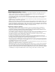
Installing the ANH-8/DC Console/Modem Cable (DB-9 Receptacle to DB-25 Plug Cable DB-25 Receptacle Null Modem Adapter Two Flange Brackets Eight #6 Flathead Screws Four #6 Roundhead Screws Four #10 Cagenut Screws and Washers Four Rubber Feet AN0037B Figure 2-1. Accessories in the ANH-8/DC Shipping Container Supplying Tools and Equipment You may need items that are not part of the ANH-8/DC shipping accessories.
Installing and Operating AN/DC and ANH-8/DC Systems Cables Unless they were specifically ordered, the Ethernet and synchronous cables necessary for your network configuration are not part of the ANH-8/DC shipping accessories. If you do not have the proper cables, contact your network administrator or see the Cable Guide for Routers and BNX Platforms.
Installing the ANH-8/DC Verifying Site Requirements Verify that your installation meet the requirements listed in this section. • • • Space Requirements Electrical Requirements Environmental Requirements Note: The AN/DC should be installed only in dedicated equipment rooms where access is limited to qualified service personnel. Space Requirements The installation site must provide a certain amount of free space around the ANH-8/DC to dissipate heat.
Installing and Operating AN/DC and ANH-8/DC Systems Environmental Requirements The ANH-8/DC installation site must meet the following environmental specifications: • • • • • Maximum Altitude: 10,000 ft (3000 m) Relative Humidity (Operating): 5% to 85%, noncondensing Maximum Humidity (Storage): 95%, noncondensing Operating Temperature: 41°F to 104°F (5°C to 40°C) stable Storage Temperature: -58°F to 113°F (-50° to 45°C) These requirements meet IEC 721-3 Class 3K3 climatic conditions while under operation
Installing the ANH-8/DC Installing the ANH-8/DC in a Rack For this procedure, you need • Four #10 cagenut screws and washers (shipped with the ANH-8/DC) • Two flange brackets and eight #6 flathead screws (shipped with the ANH-8/DC) • A Phillips screwdriver • An electronic enclosure rack Note: If the rack’s rail does not have threaded holes, you must supply and attach four cagenuts. To install the ANH-8/DC in a rack: 1. Attach a flange bracket to both sides of the ANH-8/DC.
Installing and Operating AN/DC and ANH-8/DC Systems Screws (4 places) 1 2 3 5 4 6 7 Partition 8 1 2 3 5 4 6 7 8 Link Console Boot Run DCM AUI Part DCD1 DCD2 MDI-X/MDI MDI-X Power Fault Reset AUI Col Screws (4 places) AN0040A Figure 2-3. Attaching Flange Brackets to Rack-Mount the ANH-8/DC 2. 2-8 Align the flange bracket holes with the holes in the front vertical supports of the rack (Figure 2-4).
Installing the ANH-8/DC 1 MDI-X/MDI 2 3 4 5 6 7 8 1 MDI-X Partition 2 3 4 5 6 MDI-X 7 Access Nod e Hub 8 Link Screws (4 places) Rail Cagenut If the rack rail is not threaded, attach a cagenut (not supplied). AN0041A Figure 2-4. 312410-A Rev 00 Installing the ANH-8/DC in an Electronic Enclosure Rack 3. Insert a cagenut screw through each bracket hole and into the corresponding holes in the rack. 4. Tighten each cagenut screw with a Phillips screwdriver.
Installing and Operating AN/DC and ANH-8/DC Systems Mounting the ANH-8/DC on a Wall For this procedure, you need • Two flange brackets and four #6 roundhead screws (shipped with the ANH-8/DC) • Four to eight wall anchor screws (not shipped with the ANH-8/DC) • A Phillips screwdriver Complete the following steps: 1. Attach a flange bracket to both sides of the ANH-8/DC. Note: The sides of the ANH-8/DC include screw holes at both ends, providing three ways to attach the brackets for wall-mounting.
Access Node Hub Installing the ANH-8/DC AN0043A Figure 2-6. 3. 312410-A Rev 00 Mounting the ANH-8/DC on a Wall Insert two to four wall anchor screws thwrough the holes in each flange bracket, and fasten each screw securely in the wall.
Installing and Operating AN/DC and ANH-8/DC Systems Connecting Communications Cables Gather the communications equipment and cabling that you will attach to the ANH-8/DC. If you do not have the proper cables, contact your network administrator or see the Cable Guide for Routers and BNX Platforms. Appendix C describes the ANH-8/DC cable interfaces.
Installing the ANH-8/DC Connecting Ethernet Repeater Port UTP Cables To connect unshielded twisted-pair (UTP) cables to the front panel 10Base-T repeater ports, attach the UTP cables to the front-panel RJ-45 connectors (Ethernet Repeater Ports 1-8), as shown in Figure 2-8. Ethernet repeater ports 1-8 with RJ-45 connectors Access Node Hub UTP cables AN0045A Figure 2-8.
Installing and Operating AN/DC and ANH-8/DC Systems Power Console 1 Boot Run DCM AUI Part 2 3 4 5 6 7 8 Partition AUI MDI-X/MDI Fault Reset 1 DCD1 DCD2 Col MDI-X 2 3 4 5 6 7 8 Link MDI-X/MDI AN0056A Figure 2-9.
Installing the ANH-8/DC When you configure a network with multiple ANH-8/DC (or other repeater/hub) systems, you must comply with the following rules: • Connect no more than four hubs. • Make sure that each UTP connection is not longer than 100 meters (109.4 yards). • If a transceiver is connected to the AUI port, disable the SQE (signal quality error) test function of the transceiver. Figure 2-10 shows three ANH-8/DC systems connected with straight-through cables.
Installing and Operating AN/DC and ANH-8/DC Systems ANH repeater port 1 switch set to MDI Power Console 1 Boot Run DCM AUI Part 2 3 4 5 6 7 8 Partition AUI MDI-X/MDI 1 Fault Reset DCD1 DCD2 Col 2 3 4 5 6 7 8 Link MDI-X UTP cable UTP cable Port 1 switch set to MDI Model 810 Model 810M Hub Model 810M Hub Model 810 Port 8 switch set to MDI-X AN0075A Figure 2-11. Linking Hubs Refer to “10Base-T Repeater Ports (ANH-8/DC only)” in Appendix C for more information.
Installing the ANH-8/DC Connecting a Second Ethernet Interface UTP Cable Complete these steps to connect a UTP cable to the back panel UTP-2 port. Note: This section does not apply unless you have upgraded the ANH-8/DC with a Second Ethernet Interface module. 1. Attach a UTP cable to the back-panel RJ-45 connector (Figure 2-12). -48VDC COM 3/Expansion COM 2 COM 1 -60VDC 1.5A RTN -VDC TX RX UTP-2 COL Second Ethernet UTP Cable Connector AN0047B Figure 2-12. 2.
Installing and Operating AN/DC and ANH-8/DC Systems Connecting Synchronous Cables Connect one to three synchronous interface cables to the back of the ANH-8/DC: 1. Locate the RS-232, RS-422, V.28, V.35, or X.21 interface cable. See the Cable Guide for Routers and BNX Platforms. 2. Connect the cable to the back-panel port labeled COM1, COM2, or COM3 (Figure 2-13). Note: Your ANH-8/DC may not have a third synchronous interface. The COM3/Expansion port may be empty or contain another cable interface.
Installing the ANH-8/DC Connecting an ISDN Cable Connect an ISDN BRI cable to the back of the ANH-8/DC: Note: This section does not apply unless you have upgraded the ANH-8/DC with an ISDN Basic Rate Interface module. 1. Plug the ISDN cable into the ISDN-BRI connector (Figure 2-14). -48VDC COM 3/Expansion COM 2 COM 1 -60VDC 1.5A RTN -VDC Synchronous Cables ISDN-BRI ISDN BRI Cable Connector AN0049B Figure 2-14. 2.
Installing and Operating AN/DC and ANH-8/DC Systems Connecting a Management Console or Modem Use the front-panel console port to connect an ASCII-based terminal, a personal computer terminal emulator, or a modem to the ANH-8/DC. Using a local terminal, you can monitor the results of startup diagnostics and set the boot configuration. Using an attached modem, you can allow remote dial-in access to diagnostics.
Installing the ANH-8/DC 4. Insert the screw on the cable’s connector into the receptacle on the adapter’s connector and tighten the screw (Figure 2-15). Console cable connector Null modem crossover adapter Screw receptacle Rotate to tighten screw AN0010A Figure 2-15. 5. Attaching the Null Modem Adapter Attach the 25-pin receptacle connector on the combined cable and adapter to the console’s host connector (Figure 2-16).
Installing and Operating AN/DC and ANH-8/DC Systems 6. Insert the 9-pin receptacle end of the console cable into the ANH-8/DC console port connector. The console is now connected to the ANH-8/DC. Connecting a PC Console You need both pieces in the ANH-8/DC console/modem cable kit to connect a PC: • Order No. 110307 serial console/modem cable (with 9-pin receptacle to 25-pin plug connectors) • Order No.
Installing the ANH-8/DC Access Node Hub PC cable Null modem adapter Console cable AN0051A Figure 2-17. Connecting a PC Console to the ANH-8/DC 5. Attach the 25-pin receptacle end of the cable-plus-adapter to the PC console cable’s 25-pin plug connector. 6. Connect the complete cable unit to the communications port at the back of the PC (Figure 2-17). Connecting a Modem A modem provides remote access to the ANH-8/DC for a system administrator.
Installing and Operating AN/DC and ANH-8/DC Systems Complete the following steps: 1. Configure the modem, using the parameters in Table 2-2. Refer to the modem user manual for instructions. Table 2-2. Modem Parameters Modem Signal/Parameter Value Clear To Send (CTS) On Data Terminal Ready (DTR) Depends on the modem type. Set DTR to require the modem to answer incoming calls.
Installing the ANH-8/DC Access Node Hub Modem cable AN0052A Figure 2-18. 4. 312410-A Rev 00 Connecting a Modem to the ANH-8/DC Insert the 25-pin plug at the other end of the modem cable into the modem’s RS-232 data communications port.
Installing and Operating AN/DC and ANH-8/DC Systems Connecting to the DC Power Source Danger: Due to high-energy hazards, only qualified service personnel are permitted to connect the ANH-8/DC to the power source. Ensure that the connection is to an isolated -48 V or -60 V source (reinforced insulation from the main [AC] power). To connect the ANH-8/DC to the power source: 1. Ensure that the power switch is in the OFF (0) position (Figure 2-19). 2.
Installing the ANH-8/DC DC power terminals (3) -48VDC -60VDC 1.5A RTN -VDC Power switch OFF (0) AN0094A Figure 2-20. 6. Attaching the ANH-8/DC Power Input Cables Strip 3/8 in. (10 mm) of insulation from the end of a #16 or #18 AWG cable. Note: Make certain to use the same wire gauge as that used for the minus lead. 7. Insert the stripped end of the cable into the RTN terminal block, the plus lead (Figure 2-20). 8.
Installing and Operating AN/DC and ANH-8/DC Systems Earth Ground Options -48VDC -60VDC 1.5A RTN -VDC AN0095A Figure 2-21. Attaching the ANH-8/DC Earth Ground Cable 10. Before qualified service personnel connect the ANH-8/DC to the power source, verify that the power switch is OFF and that the ANH-8/DC has been properly grounded. Danger: Once the ANH-8/DC is connected to the power source, do not remove the input wires.
Chapter 3 Starting the AN/DC and ANH-8/DC The first time you start the AN/DC or ANH-8/DC, you complete an important software configuration process. Before you begin the initial startup from a remote site: 1. Coordinate with your network administrator. The network administrator, using the manual Connecting BayStack AN and ANH Systems to a Network or Configuring Remote Access, determines which software configuration option is best for your site and configures the network to support it. 2.
Installing and Operating AN/DC and ANH-8/DC Systems You must complete an initial startup procedure to obtain the necessary files and connect the AN/DC or ANH-8/DC to the network. Getting a file over the network is called network booting, or netbooting. Getting a file from the router file system, stored in Flash memory, is called local booting. Note: This guide explains using Site Manager software to connect the router to a managed network.
Starting the AN/DC and ANH-8/DC Table 3-1. Summary of Initial Startup Options (continued) Boot Option Source for Router Image Source for Config File Directed Netboot Network (synchronous or Ethernet connection) Network (synchronous or Ethernet connection) Description and Requirements The router obtains all startup files from a remote UNIX- or DOS-based workstation that is configured as a Trivial File Transfer Protocol (TFTP) server.
Installing and Operating AN/DC and ANH-8/DC Systems 1. Position the card with the label facing up and the INSERT arrow pointing toward the card receptacle. 2. Insert the card into the receptacle. Figure 3-2 shows how to insert the Flash memory card in an AN/DC that does not have a Flash memory card protector installed. Figure 3-3 shows how to insert the card in an ANH-8/DC. 3. Gently push the card until it fits snugly into place.
Starting the AN/DC and ANH-8/DC 5 6 7 8 Partition 1 2 3 4 5 6 7 8 Link AN0061A Figure 3-3. Inserting a Flash Memory Card in the ANH-8/DC Card Receptacle Using EZ Install To use the EZ Install feature: 1. Install the router and attached communications equipment as described in Chapter 1 (AN/DC) or Chapter 2 (ANH-8/DC). There must be at least one synchronous connection to one of the COM ports.
Installing and Operating AN/DC and ANH-8/DC Systems Using Netboot, Directed Netboot, or Local Boot You use a command interface to the router software, the Diagnostic Monitor, for Netbooting or Local Booting. (You can also use the Technician Interface or Site Manager for the Directed Netboot procedure.) The AN/DC and ANH-8/DC ship with the configuration source set to network and the image source set to local.
Starting the AN/DC and ANH-8/DC AN Diagnostics: Version - 7.xx - Wed Aug 30 16:29:38 EDT 1996 MOD ID = 0x41A (1050) Flash Card instal Rev = 0x00 (00) S/N = 0xxxxxxxxx Memory = xMB TYPE "?" or "h" for HELP Test TEST TEST TEST TEST TEST TEST TEST TEST TEST TEST TEST . . .
Installing and Operating AN/DC and ANH-8/DC Systems TEST 00E TEST 00F Sync Port2 Int Loop TX Chain Test ------- PASSED Sync Port2 Int Loop RX Chain Test ------- Control-c invoked AN Diagnostics: Version - 6.01 - Mon July 24 07:54:00 EDT 1996 Login: Manager AN Diagnostics: Version - 6.01 - Mon July 24 07:54:00 EDT 1996 MOD ID = 0x40D (1037) Rev = 01 S/N = 015693 Flash = 4MB Memory = 4MB AN_DIAG>> AN00063A Figure 3-5. Logging In to the Diagnostic Monitor 6.
Starting the AN/DC and ANH-8/DC Continuing with Netboot 1. Contact your network administrator to verify that the network is set up for the Netboot procedure. 2. Ask your network administrator (or refer to Appendix A) for the interface configuration command to use in Step 3. Write the command below for reference. ifconfig _______________________ 3. Type the appropriate ifconfig command at the Diagnostic Monitor prompt and press the Return key to configure the router’s interface to the network.
Installing and Operating AN/DC and ANH-8/DC Systems AN_DIAG>> getcfg Boot Options: boot image=local boot config=network Verify NetBoot Parameters: XCVR1...IP=192.32.37.125, Mask=255.255.255.224 COM1....EZ-Install COM2....EZ-Install XCVR2...None AN_DIAG>> AN0065A Figure 3-7. Verifying the Interface Configuration Note: The location of the image and configuration file is either local or network. Local means that the an.exe or config file is stored on the router’s local file system (Flash memory card).
Starting the AN/DC and ANH-8/DC AN_DIAG>> boot Booting Access Node... Starting OS Kernel for network boot... Attempting Netboot on XCVR1 Attempting EZ-Install on COM1, using Wellfleet Pt-to-Pt Attempting EZ-Install on COM2, using Wellfleet Pt-to-Pt IP interface active on XCVR1, attempting BOOTP Received BOOTP response from server 192.32.3.9 on XCVR1 Retrieving config 'config' from network. done Found image '1:an.exe' on local file system...booting Image is in compressed format...
Installing and Operating AN/DC and ANH-8/DC Systems Continuing with Directed Netboot Before you can use the Directed Netboot procedure, you must have already used the ifconfig command (as described in the previous section) to configure the interface from which you plan to use Directed Netboot. You can use the Diagnostic Monitor, Technician Interface, or Site Manager to perform Directed Netboot. This guide assumes that you are at the router site and are using the Diagnostic Monitor.
Starting the AN/DC and ANH-8/DC 4. Type the following command and press the Return key to verify the configuration that you specified in Step 3 (Figure 3-10): getcfg Boot Options: boot image=network boot config=network host IP address=192.32.x.x image pathname= “/usr/anstartup/krnl_an.exe” config pathname= “/usr/anstartup/config” NetBoot Parameters: XCVR1...IP=192.32.x.x, Mask=255.255.255.224 COM1....EZ-Install COM2....EZ-Install XCVR2...None AN_DIAG>> AN0020A Figure 3-10.
Installing and Operating AN/DC and ANH-8/DC Systems Booting Access Node... Starting OS kernel for network boot... Attempting Directed Netboot. Directed Netboot using active IP interface XCVR1. Retrieving config 'config' from network. done Retrieving image 'krnl_an.exe' from network......done Nortel Networks, Inc. and its Licensors. Copyright 1992, 1993, 1994, 1995, 1996, 1997, 1998. All rights reserved. Login: AN0070A Figure 3-11.
Starting the AN/DC and ANH-8/DC Continuing with Local Boot You need to use both the Diagnostic Monitor and the Technician Interface to local boot the AN. Before starting the Local Boot procedure, ask your network administrator for assistance in completing the Quick-Start worksheets in Appendix B. To use the Local Boot feature: 1. Contact your network administrator to verify that the network is set up for the Local Boot procedure. 2.
Installing and Operating AN/DC and ANH-8/DC Systems Booting Access Node... Attempting local configuration and boot... Configuration file '1:config' successfully loaded. Found image '1:an.exe' on local file system...booting Image is in compressed format... decompressing Nortel Networks, Inc. and its Licensors. Copyright 1992, 1993, 1994, 1995, 1996, 1997, 1998. All rights reserved Login: AN0071A Figure 3-12.
Starting the AN/DC and ANH-8/DC Nortel Networks, Inc. and its Licensors. Copyright 1992, 1993, 1994, 1995, 1996, 1997, 1998. All rights reserved. Login: Manager Mounting new volume... Device label: Directory: 1: New Present Working Directory: 1: Welcome to the Backbone Technician Interface [1:1]$ AN0024A Figure 3-13.
Installing and Operating AN/DC and ANH-8/DC Systems 8. When the Technician Interface prompt reappears, type the following command and press the Return key to exit the Technician Interface: logout Once the install script completes, the router starts bridging and routing traffic. Note: If the router tries to Local Boot and cannot get a software image, it attempts to Netboot once. If both the Local Boot and Netboot attempts fail, the AN Diagnostic Monitor Login prompt appears on the console.
Chapter 4 Operating the AN/DC and ANH-8/DC This chapter describes • Ensuring a Successful Installation (using the front-panel LEDs) • Checking the status of the router using -- AN/DC LED Descriptions -- ANH-8/DC LED Descriptions 312410-A Rev 00 • Powering On and Off • Resetting the AN/DC or ANH-8/DC • Removing a Flash Memory Card • Protecting Memory Card Files 4-1
Installing and Operating AN/DC and ANH-8/DC Systems Ensuring a Successful Installation After connecting the router to the network, you can ensure a successful installation by checking the LEDs on the front panel. Figure 4-1 shows the front-panel LEDs on an AN/DC. RUN BOOT DIAG POWER RUN BOOT DIAG POWER AN0025A Figure 4-1. AN/DC Front-Panel LEDs Figure 4-2 shows the front-panel LEDs on an ANH-8/DC.
Operating the AN/DC and ANH-8/DC When power is supplied to the router, the following LED sequence should occur: • The POWER LED lights and remains on. • RUN, BOOT, and DIAG (or FAULT for ANH) LEDs light for approximately 1 second, then turn off, indicating that the router is functioning. • The RUN LED blinks for 1 to 3 minutes, indicating that the diagnostic tests are running. (It blinks quickly during the initial 17-second memory test, then slows down during the interface tests.
Installing and Operating AN/DC and ANH-8/DC Systems AN/DC LED Descriptions LEDs on the AN/DC front and back panels provide information about how the AN/DC is operating. The following sections describe the AN/DC front- and back-panel LEDs. For information on the ANH-8/DC LEDs, see ANH-8/DC LED Descriptions. Front-Panel LEDs Table 4-1 describes the AN/DC front-panel LEDs. These LEDs indicate the status of the AN/DC itself. All front-panel LEDs light briefly when the AN/DC first receives power. Table 4-1.
Operating the AN/DC and ANH-8/DC Back-Panel LEDs The LEDs on the AN/DC back-panel differ depending on the AN/DC model that you have. Table 4-2 describes all of the available AN/DC back-panel LEDs. These LEDs indicate the status of the AN/DC’s network connections. Table 4-2. Back-Panel LEDs LED Meaning Ethernet/Second Ethernet interface (XCVR or UTP) TX (Transmit) Lights when the AN/DC is transmitting data over the network. RX (Receive) Lights when the AN/DC is receiving data from the network.
Installing and Operating AN/DC and ANH-8/DC Systems ANH-8/DC LED Descriptions LEDs on the ANH-8/DC front and back panels provide information about how the ANH-8/DC is operating. Front-Panel LEDs Figure 4-2 shown earlier illustrates the three sets of status LEDs on the ANH front panel. Table 4-3 describes the function of each front-panel LED. Note: All front-panel LEDs light briefly when you turn on the ANH-8/DC; this simply indicates that the ANH-8/DC is receiving power. Table 4-3.
Operating the AN/DC and ANH-8/DC Table 4-3. ANH-8/DC Front-Panel LEDs (continued) LED Label Color Meaning AUI Part (Partition) Amber Lights to indicate that the AUI port has been partitioned from the repeater due to a disruption in transmission. Autopartitioning occurs after an excessive number of consecutive collisions or an excessively long single-collision signal. DCD1 (Data Carrier Detect 1) Green Lights to indicate that the first synchronous port (COM1) is active.
Installing and Operating AN/DC and ANH-8/DC Systems Table 4-4 describes the back-panel LEDs. Table 4-4. Back-Panel LEDs LED Color Meaning TX (Transmit) Green Lights when the ANH-8/DC is transmitting data over the network. RX (Receive) Green Lights when the ANH-8/DC is receiving data from the network. COL (Collision) Amber Lights when the ANH-8/DC detects a collision on the network. Green Lights when S/T interface is active; turns off when interface is inactive.
Operating the AN/DC and ANH-8/DC UL UL -48VDC -60VDC COM 1 1.5A RTN -VDC Power switch OFF (0) AN0091A Figure 4-4. AN/DC Power Switch Power switch COM 3/Expasion COM 2 COM 1 AN0054A Figure 4-5. ANH-8/DC Power Switch 2. Verify that air is flowing by placing your hand to the side of the fan vents. Note: If you cannot feel air flow from the vents, and the POWER and DIAG LEDs do not light or the DIAG LED does not turn off, turn the power switch to the OFF position.
Installing and Operating AN/DC and ANH-8/DC Systems Resetting the AN/DC or ANH-8/DC You can use the Reset button to reboot the router hardware without cycling power, as follows: • To warm-boot the router (no diagnostic tests run), press the Reset button for less than 3 seconds. • To cold-boot the router (diagnostic tests run), press the Reset button for more than 3 seconds. To activate the Reset button, use a small pointed object (for example, a paper clip) to press the button.
Operating the AN/DC and ANH-8/DC AN/DC Reset Switch On the AN/DC, the Reset button is located on the back panel of the AN/DC (Figure 4-6). Labeled “RST,” it resides between the console port and the LED labeled “RLSD2.” UL UL -48VDC -60VDC 1.5A XCVR COM 2 CONSOLE UTP TX RX CL COM 1 RST RTN RLSD2 RLSD1 Reset Button Figure 4-6. -VDC AN0014B AN/DC Reset Button ANH-8/DC Reset Switch On an ANH-8/DC, the Reset button is set inside the front panel (Figure 4-7).
Installing and Operating AN/DC and ANH-8/DC Systems Removing a Flash Memory Card When you remove a formatted memory card, the NVFS automatically removes access to the card. When you insert and format a card or insert an already formatted card, the NVFS automatically provides access. To remove a memory card from an AN/DC or ANH-8/DC: 1. Press the eject button adjacent to the card receptacle on the front panel. Figure 4-8 shows the eject button on an AN/DC. Figure 4-9 shows the eject button on an ANH-8/DC.
Operating the AN/DC and ANH-8/DC Protecting Memory Card Files Nortel Networks ships each memory card with its read-write protect switch in the unprotected position (Figure 4-10). After successfully loading the configuration file and saving your configuration, you may want to write-protect the memory card for backup purposes. Note: You typically do not operate the router with a write-protected memory card.
Installing and Operating AN/DC and ANH-8/DC Systems 4-14 312410-A Rev 00
Appendix A Configuring Netboot and Directed Netboot You can use the following commands to configure the AN/DC or ANH-8/DC for Netboot and Directed Netboot: • Use the ifconfig command to configure the router’s initial IP interface to the network. You need this information to complete the procedure in “Continuing with Netboot” in Chapter 3. • Use the bconfig command to specify the location and name of the AN/ANH software image and configuration file.
Installing and Operating AN/DC and ANH-8/DC Systems Configuring a Synchronous IP Interface for Netbooting To Netboot, you must first configure the router’s initial IP interface to the network, using the following interface configuration command: ifconfig [synchronous options] [] [synchronous options] indicates some combination of the following settings: [-d | -fr [ -annexd | -annexa | -lmi ] | -int_clk] Note: You must insert a space to separate each command op
Configuring Netboot and Directed Netboot Table A-1. The ifconfig Command Settings for a Synchronous Interface (continued) Setting Description Internal clocking setting: Sets the synchronous port to internal clocking at 1.25 Mb/s. If you do not specify the -int_clk setting, the AN/DC or ANH-8/DC defaults to external clocking. -int_clk IP connector setting: Specifies the type of IP connector you are configuring. Use com1 or com2 (for synchronous media).
Installing and Operating AN/DC and ANH-8/DC Systems Table A-2. The ifconfig Command Settings for an Ethernet Interface (continued) Setting Description IP address settings: Specifies the IP address of the interface you set with . Provide this address in dotted decimal notation. Specifies the IP subnet mask of the interface you selected with the setting. Provide this address in dotted decimal notation.
Configuring Netboot and Directed Netboot Table A-3. The bconfig Command Options Option Description image Specifies information about the software image. config Specifies information about the configuration file. local Indicates that the specified file (image or config) resides in the router’s local file system. network Indicates that the specified file resides on a network server. Specifies the IP address of the host where the image or configuration file resides.
Installing and Operating AN/DC and ANH-8/DC Systems A-6 312410-A Rev 00
Appendix B Using Local Boot (the Quick-Start Procedure) You can local boot the AN/DC or ANH-8/DC using the Site Manager Quick-Start procedure explained in this appendix. You need this information to complete the procedure in “Continuing with Local Boot” on page 3-15 . The Quick-Start procedure is the initial configuration that starts a Nortel Networks router running on the network. The procedure enables the Internet Protocol (IP) so that the router can connect to Site Manager.
Installing and Operating AN/DC and ANH-8/DC Systems Filling Out the Quick-Start Worksheets The install.bat script provides many options for configuring the router on a network. Note: Because typical remote access uses a synchronous interface over a WAN connection, this section lists only the options involved with a synchronous configuration. When you configure a LAN interface, base your decision on the information provided with each install.bat prompt.
Using Local Boot (the Quick-Start Procedure) Global Information Worksheet This section contains the prompts and possible options relating to all AN/ANH synchronous configurations. Write your selection in the “Your Response” column. Global Information Worksheet Step Requested Information Options Your Response 1 Specify the slot number where the Link Module resides. Because the AN/DC and ANH-8/DC is not a Link Module, the script bypasses this step and automatically accepts a default slot of “1.” None.
Installing and Operating AN/DC and ANH-8/DC Systems Global Information Worksheet (continued) Step Requested Information Options Your Response 3 Enter IP address in dotted decimal notation: Enter the IP address for the COM interface. Enter the subnetwork mask in dotted decimal notation: Enter the subnetwork mask for the COM interface IP address. Is the router connected to the same local area network as the Site Manager workstation? (y/n) [n]: y(es) n(o) Press the Return key.
Using Local Boot (the Quick-Start Procedure) Router Protocol Worksheets This section contains requested information and possible options relating to the routing protocol choices on the Global Information Worksheet. RIP Worksheet Requested Information Options Should RIP listen to the default route? (y/n) [n]: y(es) n(o) Your Response Note: RIP listens to a specific network or subnet route where Site Manager is located. Answering y(es) to this request forces RIP to also listen to the default route (0.0.
Installing and Operating AN/DC and ANH-8/DC Systems OSPF Worksheet (continued) Requested Information Options Enter OSPF MTU size selection [1]: 1. Default 2. Ethernet size (Nortel Networks Series 5 compatible) 3. User defined MTU Enter OSPF interface type selection [1]: 1. 2. 3. 4. 5. Your Response Broadcast NBMA Point-to-Point Point-to-Multipoint Point-to-Multipoint (STD) Note: When using a wide area protocol other than Nortel Networks Proprietary PPP, we suggest selecting NBMA.
Using Local Boot (the Quick-Start Procedure) OSPF Worksheet (continued) Requested Information Options Enter decimal value in seconds for Poll Interval [20]: Enter the largest number of seconds allowed between Hello packets that the router sends to an inactive NBMA neighbor. Your Response (For NBMA only) The router suggests a 20-second interval. Enter IP address of neighbor in dotted decimal notation or enter q to quit: Enter addresses for all NBMA neighbors you want the router to communicate with.
Installing and Operating AN/DC and ANH-8/DC Systems Static Route to Site Manager Worksheet Requested Information Options Destination Network [0.0.0.0]: Enter the gateway address of the destination network. An address of 0.0.0.0 specifies the default route. Destination Network Mask [0.0.0.0]: Enter the subnetwork mask of the destination network. A mask of 0.0.0.0 specifies the default route. Next-Hop Address: Enter a next-hop address.
Using Local Boot (the Quick-Start Procedure) Wide Area Protocol Worksheets This section contains requested information and possible options relating to wide area protocol choices on the Global Information Worksheet. Nortel Networks Proprietary PPP Worksheet Requested Information Options Enter BOFL (Breath of Life) timer value (1-60) [5]: Enter the maximum amount of time that can elapse between the successful transmission of BofL messages. Enter Local Address Selection [3]: 1. DCE 2. DTE 3.
Installing and Operating AN/DC and ANH-8/DC Systems Frame Relay Worksheet Requested Information Options Enter address field length: 2. Two Bytes 3. Three Bytes 4. Four Bytes Enter DLCI number [30]: Enter the Permanent Virtual Circuit (PVC) number. Your Information (For DLCMI None, LMI Switch, Annex D Switch, and Annex A Switch only) Note: The valid range for the DLCI number is between 16 and 1007.
Using Local Boot (the Quick-Start Procedure) PPP Standard Worksheet (continued) Requested Information Options Enable the LQR (Link Quality Reporting) Protocol? (y/n) [n]: y(es) n(o) Your Information Note: Link Quality Monitoring on a Nortel Networks Series 5 router is not compatible with this feature.
Installing and Operating AN/DC and ANH-8/DC Systems SMDS Worksheet Requested Information Options Your Information Enter 10-digit individual address: Enter the individual address assigned to you by your SMDS service provider. Enter 10-digit group address: Enter the group address assigned to you by your SMDS service provider. Enter 10-digit arp address: Enter the Address Resolution Protocol (ARP) address assigned to you by your SMDS service provider.
Using Local Boot (the Quick-Start Procedure) Running the Quick-Start Script After you enter run install.bat, the AN/DC or ANH-8/DC progresses through the Quick-Start script as follows: 1. The script begins prompting you for the initial Global Worksheet information. 2. After you select a router protocol option, the script prompts for specific protocol information. 3. After finishing the router protocol configuration, the script requests a wide area protocol selection. 4.
Installing and Operating AN/DC and ANH-8/DC Systems B-14 312410-A Rev 00
Appendix C Technical Specifications This appendix provides • • • • • • AN/DC Physical Specifications ANH-8/DC Physical Specifications Power Supply Specifications AN/DC Hardware Communications Options ANH-8/DC Hardware Communications Options Connector Pinouts AN/DC Physical Specifications The dimensions and weight of the AN/DC are • • • • Height: 3.3 in. (8.4 cm) Width: 17.5 in. (44.5 cm) Depth: 9.5 in. (24.1 cm) Weight: 12 lb (5.
Installing and Operating AN/DC and ANH-8/DC Systems Power Supply Specifications Specifications for both the AN/DC AN and ANH-8/DC power supply: • Nominal input voltage of -48 or -60 DC, +/- 20% • 3 DC output voltages (5, 12, and 12), for a total output power of 43 watts with forced air cooling AN/DC Hardware Communications Options The AN/DC is available with one Ethernet AUI and two synchronous interfaces.
Technical Specifications Table C-1. AN/DC Network Interfaces Network Interface Description Ethernet and Second Ethernet Supports the Ethernet and IEEE 802.3 standards that provide LAN connectivity. The Ethernet interfaces on an AN/DC include a 10Base-T (UTP) and an 802.3 AUI (XCVR) port; however, you can use only one port at a time.
Installing and Operating AN/DC and ANH-8/DC Systems ANH-8/DC Hardware Communications Options Every ANH-8/DC includes • • • 9 Ethernet LAN repeater ports (1 AUI and 8 UTP) 2 synchronous wide area network (WAN) ports 1 local console service port Note: The Ethernet repeater ports operate as a single interface. Software configuration parameters (for example, the port IP address) apply to all ports.
Technical Specifications Table C-2. Network Interface Ethernet ANH-8/DC Network Interfaces Description The ANH-8/DC supports eight 10Base-T UTP repeater ports and one 802.3 AUI port; however, you can use only one port at a time. These interfaces comprise a single managed segment, supporting the Ethernet and IEEE 802.3 standards that provide LAN connectivity. Some ANH-8/DC models also include an Ethernet UTP port on the back panel. This second Ethernet interface is not a repeater port.
Installing and Operating AN/DC and ANH-8/DC Systems Attachment Unit Interface (AUI) Ports The AN/DC back panel and ANH-8/DC front panel contains a standard 802.3 AUI DB-15 receptacle connector with a slide lock for connection to the AUI. You can use the Order No. 7115 Ethernet cable, described in the Cable Guide for Routers and BNX Platforms, for connections to this port.
Technical Specifications 10Base-T Repeater Ports (ANH-8/DC only) The eight Ethernet 10Base-T repeater port RJ-45 connectors on the ANH-8/DC front panel provide UTP support. The ANH-8/DC transmits the same information over each repeater port; it allows simultaneous connection to any of the eight 10Base-T ports or AUI port. Each of the eight shielded RJ-45 jacks is a 10Base-T port using the standard media-dependent interface with internal crossover (MDI-X) pin assignment.
Installing and Operating AN/DC and ANH-8/DC Systems Synchronous Interfaces The AN/DC and ANH-8/DC support two synchronous interfaces, labeled COM1 and COM2. Systems with a Third Synchronous Interface or ISDN BRI upgrade module support a third synchronous port. The synchronous interfaces provide multiprotocol WAN connection through DB-44 receptacle connectors. Each synchronous interface can operate independently with RS-232, RS-422, V.35, and X.
Technical Specifications Table C-5. Synchronous Port Pin Assignments Pin Assignment Pin 15 Pin 1 Pin 30 Pin 16 Pin 44 Pin 31 312410-A Rev 00 Pin No. Signal Name Pin No.
Installing and Operating AN/DC and ANH-8/DC Systems ISDN BRI Ports The AN/DC and ANH-8/DC support the BRI standard for ISDN using an optional ISDN/BRI module. The integrated ISDN BRI functionality allows you to connect directly to the ISDN network, as opposed to connecting via a terminal adapter. This solution reduces equipment costs and simplifies connection to an ISDN switch. The BRI implementation supports two dial service applications: dial-on-demand and dial backup.
Technical Specifications The AN/DC and ANH-8/DC shipping package includes the Order No. 110310 console/modem kit for connecting devices to the Console port. • To connect a modem to the Console port, use the Order No. 110307 cable, a standard, 15-foot molded AT serial cable with DB-9 receptacle to DB-25 plug connectors. • To connect a terminal to the Console port, use the complete console/modem kit (the Order No. 110307 cable with the Order No.110308 null modem adapter).
Installing and Operating AN/DC and ANH-8/DC Systems C-12 312410-A Rev 00
Appendix D Requirements for European Operation This appendix provides information required for operating the AN/DC and ANH-8/DC in Europe. ANH-8/DC Safety Status Tables D-1, D-2, and D-3 list the safety status of interconnection points to the connection of other equipment. Table D-1. Port Location Port Description Type of Circuit COM1 V.28, X.21, V.35 TNV (Telecommunications Network Voltage) at SELV (Safety Extra-Low Voltage) levels COM2 V.28, X.21, V.35 TNV at SELV levels Console V.
Installing and Operating AN/DC and ANH-8/DC Systems Table D-3. Safety Status (Order Nos. AE0004006, AE0011013, and AEE0011019) Port Location Port Description Type of Circuit ISDN BRI ISDN TNV at SELV levels P6 Host Port SELV AN/DC Safety Status Table D-4 lists the safety status of interconnection points to the connection of other equipment. Table D-4. Safety Status (Order Nos. AE1001037, AE1001038, AE1001039, and AE1001040) Port Location Port Description Type of Circuit COM1 V.28, X.21, V.
Requirements for European Operation Synchronous Cabling Requirements Refer to Figure D-1 through Figure D-3 and Table D-6 through Table D-8 for synchronous interface cabling information. Note the following compliance requirements: • V.28 compliance requires the use of an Order No. 7837 cable • V.35 compliance requires the use of an Order No. 7220 cable • X.21 compliance requires the use of an Order No.
Installing and Operating AN/DC and ANH-8/DC Systems Table D-6. WAN Interface (Order No.
Requirements for European Operation Table D-7. V.35 Interface (Order No.
Installing and Operating AN/DC and ANH-8/DC Systems 15 FEET Pin 1 Pin 15 Pin 16 Pin 30 Pin 31 Pin 44 Pin 1 Pin 13 Pin 14 Pin 25 25-position D-SUB plug with screw locks ground shield connected to backshell 44-position D-SUB plug with screw locks ground shield connected to backshell AN0078A Figure D-3. Cable 7224 (X.21 Compliant) Table D-8. X.21 Interface (Order No.
Requirements for European Operation ISDN BRI Requirements The ISDN BRI module (Order Nos. AE0004006, AE0011013, and AE0011019 for the ANH-8/DC) and ISDN BRI upgrade module (Order Nos.
Installing and Operating AN/DC and ANH-8/DC Systems ISDN BRI Clearances and Creepage Distances The clearances and creepage distances (shown as X and Y, respectively, in Figure D-4 and Table D-10) must be maintained between the card and • The host chassis in which it is installed • Any adjacent cards installed in the host chassis The exception to this rule is the edge connector, which resides in the host chassis backplane where no minimum distance applies.
Requirements for European Operation Table D-10. ISDN BRI Clearances and Creepage Distances Clearance (X) Creepage (Y) Voltage used or generated by other parts of the host or expansion card 2.0 mm 2.4 (3.8) mm Up to 50 V rms or V dc 2.6 mm 3.0 (4.8) mm Up to 125 V rms or V dc 4.0 mm 5.0 (8.0) mm Up to 250 V rms or V dc 4.0 mm 6.4 (10.0) mm Up to 300 V rms or V dc The creepage distances apply to the normal office environment.
Installing and Operating AN/DC and ANH-8/DC Systems ISDN BRI Connector Pinouts Table D-12 lists the ISDN connector pinouts. Table D-12.
Index Numbers 10Base-T ports (ANH-8/DC), 2-13, 2-17, C-7 A AN/DC connecting to the power source, 1-18 dimensions, C-1 installing in an electronic enclosure rack, 1-6 on a flat surface, 1-6 on a wall, 1-9 LEDs.
straight-through, 2-14, C-7 supplying, 2-4 synchronous, C-8 PC, 1-15, 2-22 port, 1-13, C-10 terminal, 1-12, 1-13, 2-20, 2-22 cagenuts, for electronic enclosure rack, 1-7 conventions, text, xviii clocking, A-2 crossover switch See also MDI-X/MDI switch cold boot, 4-10 collision detection AN/DC CL (Collision) LED, 4-5 ANH-8/DC COL (Collision) LED, 4-7, 4-8 commands bconfig, 3-15, A-4 defined, 3-6 boot, 3-10, 3-13, 3-15 dir, 3-17 getcfg, 3-9, 3-13 ifconfig, 3-9, A-1 to A-3 logout, 3-18 Quick-Start, B-12
electronic enclosure rack installing AN/DC in, 1-6 installing ANH-8/DC in, 2-7 physical specifications, 1-4 ANH-8/DC in an electronic enclosure rack, 2-7 on a flat surface, 2-6 on a wall, 2-10 preparing for, 2-1 to 2-6 cagenuts in electronic enclosure rack, 1-7 flange brackets on AN/DC, 1-7 on ANH-8/DC, 2-10 environmental specifications AN/DC, 1-5 ANH-8/DC, 2-6 Ethernet AN/DC interface connections, C-2 AUI port (ANH), C-7 AUI port (ANH-8/DC), 2-12 repeater connections (ANH-8/DC), C-5 repeater ports, C-4 U
Power, 4-6 Run, 4-6 RX (Receive), 4-8 TX (Transmit), 4-8 LEDs, AN/DC POWER, 4-4 O OSPF worksheet, B-5 overheating preventing AN/DC from, 1-5 preventing ANH-8/DC from, 2-5 linking ANH-8/DCs, 2-14 Local Boot attaching a console, 1-12, 2-20 definition, 3-2 requirements, 3-3 using, 3-6, 3-15 to 3-18 P local file system, viewing, 3-17 pin assignments Ethernet repeater ports, C-7, C-8 ISDN port connector, C-10 RS-232 service port connector, C-11 M MDI-X/MDI switch, 2-13 example configurations, 2-14 using, 2
R resetting, 4-10 starting Directed Netboot, 3-6 EZ Install, 3-5 Local Boot, 3-6 Netboot, 3-6 RIP worksheet, B-5 support, Nortel Networks, xxi RLSD1 (Received Line Signal Detection 1) LED, 4-5 switches MDI-X/MDI, 2-13 repeater ports (ANH-8/DC) 10Base-T, 2-13, 2-17, C-7 RLSD2 (Received Line Signal Detection 2) LED, 4-5 RMON (Remote Monitoring) DCM, 4-6 RS-232 connections console (service) port, C-10 WAN, C-8 RS-232 service port, C-8 Sync port cables RS-232, D-5 V.
W wall-mounting AN/DC, 1-9 ANH-8/DC, 2-10 warm boot, 4-10 X X.