
Ethernet Switch Installation Guide


Installation and Reference for the BayStack 70 Series 10/100 Ethernet Switches
1-6
206375-A
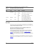
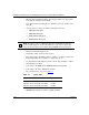
Table 1-1. Description of Switch and Port Status LEDs
Rear Panel
This section provides rear panel details for the BayStack 70-8T 10/100 Ethernet
Switch and BayStack 70-16T 10/100 Ethernet Switch and separate details for the
BayStack 70-24T 10/100 Ethernet Switch.
Rear Panel of the BayStack 70-8T 10/100 Ethernet Switch and
BayStack 70-16T 10/100 Ethernet Switch
The rear panel of the BayStack 70-8T 10/100 Ethernet Switch and BayStack
70-16T 10/100 Ethernet Switch contains a power receptacle for the AC to DC
power adapter that ships with the switch. Refer to “
DC Power Adapter” on
page 1-8 for details regarding the power adapters. A label on the rear panel
displays the date, manufacturing model number, order number, and serial number
of the switch.
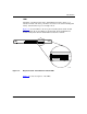
The rear panel of the BayStack 70-8T 10/100 Ethernet Switch and rear panel of
the BayStack 70-16T 10/100 Ethernet Switch are identical and are illustrated in
Figure 1-5
.
Type Label Color Activity Description
Port Status 10/100
Link/Activity
Yellow On Port is connected at 10 Mb/s.
Yellow Blinking 10 Mb/s activity is occurring on the port.
Green On Port is connected at 100 Mb/s.
Blinking 100 Mb/s activity is occurring on the port.
Off No link is established on the port.
Port Mode HDX/FDX Green On Port is operating in full-duplex mode.
Off Port is operating in half-duplex mode.
Power Power Green On Power is being supplied to the switch.
Off Power is not being supplied to the switch.