
Bridge/Router Installation Guide

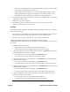

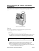


Board/Connector Relationship
Figure 3-2 illustrates the relationship between PC boards { XE "Standalone:Board/connector
relationship" }attached to the bulkhead inside the cabinet and the connectors on the exterior
surface of the cabinet.
There is a LINE PRINTER/NETWORK connector on the bottom left side of the cabinet.
Only the LINE PRINTER connector is used in a standalone configuration.
tiger021
KEYBOARD MOUSE
MONITOR
LIN E PRINTER
NETWORK
INPUT POW ER
PRTCON
No Board R equired for
Monitor
(
Pass Throu
g
h
)
KEMCON
CAMERA
CONTROLLER
BOARD
SCANNER
CONTROLLER
MAIN BOARD
Figure 3 – 2: Standalone Board/Connector Locations
Page 24 5000i Scanner Installation Guide