
Switch User Manual

Alteon OS Application Guide
Chapter 3: VLANs
8542C4911, January 2007
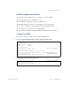
Example 1: Multiple VLANs with Tagging Adapters
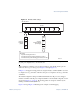
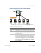
Figure 3-6 Example 1: Multiple VLANs with VLAN-Tagged Gigabit Adapters
The features of this VLAN are described below:
Component Description
GbE Switch
Module
This switch is configured for three VLANs that represent three differ-
ent IP subnets. Two servers and five clients are attached to the switch.
Server #1 This server is a member of VLAN 3 and has presence in only one IP
subnet. The associated internal switch port is only a member of VLAN
3, so tagging is disabled.
Server #2 This high-use server needs to be accessed from all VLANs and IP sub-
nets. The server has a VLAN-tagging adapter installed with VLAN tag-
ging turned on. The adapter is attached to one of the internal switch
ports, that is a member of VLANs 1, 2, and 3, and has tagging enabled.
Because of the VLAN tagging capabilities of both the adapter and the
switch, the server is able to communicate on all three IP subnets in this
network. Broadcast separation between all three VLANs and subnets,
however, is maintained.
BladeCenter
GbE
Switch Module
Switch Module
GbE
VLAN #3
VLAN #1, 2, 3