
- Nortel Ethernet Routing Switch Owner's Manual


Hardware components of the Ethernet Routing Switch 2500 Series 29
Label Type
Color State
Meaning
Steady Station connected at 10/100 Mb/s.Green
Flashing Traffic activity at 10/100 Mb/s.
Link/Act Port conne
ction status
Off No link/No traffic.
Green Steady Power is supplied to the port.PoE (applie
s to PWR
models
only)
PoE port
power
status
Off No power is supplied to the port.
Green ON This unit is permanent base in stack
mode.
Base Base unit
status for
stack mode
Amber ON This unit is selected as temporary base
in stack mode.
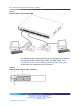
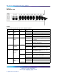
Back panel
The back panel of the Ethernet Routing Switch 2500 Series is shown in
Figure 7 " Ethernet Routing Switch 2500 Series back panel" (page 29).
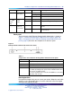
Table 3 "Components on the Ethernet Routing Switch 2500 Series back
panel" (page 29) describes the components on the back panel.
Figure 7
Ethernet Routing Switch 2500 Series back panel
Table 3
Components on the Ethernet Routing Switch 2500 Series back panel
Item Description
1
AC power receptacle
2
Kensington lock
3
Base Unit select switch
4
Additional 1000BaseT RJ-45 connector rear ports.
For switch operating mode: ports 27,28 on 2526T models and
ports 51,52 on 2550T models.
For stack operating mode: Link UP, Link DOWN for connecting
with other units in stack.
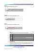
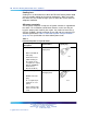
Kensington lock
Using the Kensington lock, you can secure your switch. Wrap the steel cable
around a secure immovable object, insert the cable lock in the Kensington
Security Lock, and turn the key.
Nortel Ethernet Routing Switch 2500 Series
Overview — System Configuration
NN47215-500 (323162-B) 02.02 Standard
4.1 19 November 2007
Copyright © 2007, Nortel Networks
.