
User's Manual
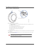
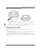
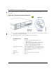

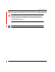
Table Of Contents
- Nortel WLAN Access Point 2332 Series Installation Guide
- Contents
- How to get help
- Introducing the Nortel WLAN 2332 Series System
- AP overview
- Installing and connecting an 2332 Series
- External Antennas

54 Installing and connecting an 2332 Series
NN47250-302 (324136-A Version 01.02)
Figure 30 shows how to insert a Cat-5 cable into a 10/100 Ethernet port on a WSS. Refer to this figure as you perform
the procedure.
Figure 30. 10/100 Cat-5 Cable Installation
1 Insert a Cat-5 cable with a standard RJ-45 connector as shown in Figure 30. For connection to an AP, use
the supplied Cat-5 straight-through cable.
2 When the link is activated, observe the AP LED for the port on the WSS:
AP LED Appearance Meaning
Solid green For an AP’s active link, all the following are true:
• AP has booted.
• AP has received a valid configuration from the WSS.
• Management link with an AP is operational.
• At least one radio is enabled or is in sentry mode.
For an AP’s secondary link, the link is present.
Alternating green and amber AP is booting with an image received from the WSS. After
the access point boots and receives its configuration, this
LED appearance persists until a radio is enabled or is
placed in sentry mode.
Solid amber PoE is on.
Blinking amber AP is unresponsive or there is a PoE problem.
Unlit PoE is off.