
User's Manual
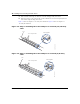
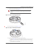
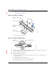
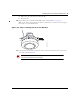
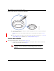
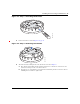
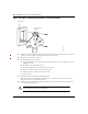
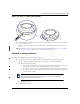
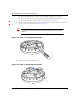
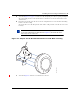
Table Of Contents
- Nortel WLAN Access Point 2332 Series Installation Guide
- Contents
- How to get help
- Introducing the Nortel WLAN 2332 Series System
- AP overview
- Installing and connecting an 2332 Series
- External Antennas

Installing and connecting an 2332 Series 51
Nortel WLAN Access Point 2332 Series Installation Guide
5 As shown in Figure 27 on page 51, feed the Cat-5 cable through the port connector opening and align the
universal mounting bracket over the drywall anchors so that the two screw holes in the bracket face the
drywall anchors.
6 Insert the #6 sheet metal screws into the screw holes, and tighten them to secure the universal mounting
bracket to the wall or ceiling.
(If you routed the Cat-5 cable through a hole in the wall or ceiling, insert the screw into the center screw
hole only.)
Figure 27. Steps 5 and 6—Bracket Placement on Solid Wall or Ceiling
7 As shown in Figure 28, insert the Cat-5 cable into the connector:
Note. Do not insert screws in the four holes on the edges of the bracket. (These
are the holes indicated by the dashed lines in Figure 27.) The AP fits into these
holes. They are not screw holes.
840-9502-0015