
User's Manual
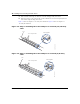
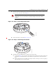
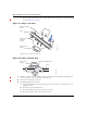
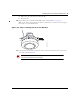
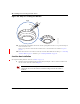
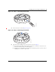
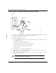
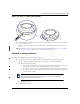
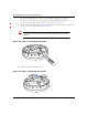
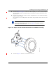
Table Of Contents
- Nortel WLAN Access Point 2332 Series Installation Guide
- Contents
- How to get help
- Introducing the Nortel WLAN 2332 Series System
- AP overview
- Installing and connecting an 2332 Series
- External Antennas

Installing and connecting an 2332 Series 49
Nortel WLAN Access Point 2332 Series Installation Guide
Figure 24. Step 7—Locking the Bracket
9 To ensure that the AP is fully locked onto the bracket, gently pull down on the access point and attempt to
rotate it from side to side.
If the access point comes off the bracket, relock the device onto the bracket as described in step 8 on
page 48.
10 If the other end of the Cat-5 cable is not already connected and the link activated, go to “Connecting an
AP to a WSS” on page 53. Otherwise, go to “Verifying AP health” on page 55.
Solid wall or ceiling installation
(For required mounting hardware and tools, see Table 3 on page 36.)
1 Prepare holes in the wall or ceiling for the universal mounting bracket, using the following steps:
a Place the paper mounting template over the location where you want to install the AP.
b Mark the screw hole location(s).
❥ If you plan to route the Cat-5 cable externally along the wall or ceiling, mark the locations of
both the center screw hole and the screw hole by the port connector opening.
❥ If you plan to route the Cat-5 cable through a hole in the wall or ceiling, mark the location of
the center screw hole only. You cannot use the screw hole by the port connector opening if you
cut a hole for the opening.
c Remove the template.
2 Install the drywall anchor(s):
Note. Do not mark the four holes on the edges of the bracket. (These are the
holes indicated by the dashed lines in Figure 27 on page 51.) The AP fits into
these holes. They are not screw holes.
840-9502-0062
Lock