
User's Manual
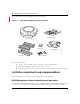
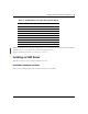
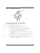
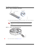
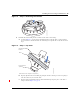
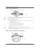
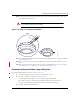
Table Of Contents
- Nortel WLAN Access Point 2332 Series Installation Guide
- Contents
- How to get help
- Introducing the Nortel WLAN 2332 Series System
- AP overview
- Installing and connecting an 2332 Series
- External Antennas

Installing and connecting an 2332 Series 41
Nortel WLAN Access Point 2332 Series Installation Guide
12 Lock the AP onto the bracket by inserting the 3-mm or 1/8-inch screwdriver into the Lock hole on the
access point as shown in Figure 12.
Figure 12. Step 12—Locking the Bracket
13 To ensure that the AP is fully locked onto the bracket, gently pull down on the access point and attempt to
rotate it from side to side.
14 If the access point comes off the bracket, relock the device onto the bracket as described in step 12 on
page 41.
15 If the other end of the Cat-5 cable is not already connected and the link activated, go to “Connecting an
AP to a WSS” on page 53. Otherwise, go to “Verifying AP health” on page 55.
Suspended ceiling installation—drop ceiling tiles
(For required mounting hardware and tools, see Table 3 on page 36.)
1 Select an installation location that is centered over a T-bar in the ceiling.
2 Cut a hole as follows in the ceiling tile for the Cat-5 cable:
a Place the mounting template over the area where you plan to install the AP.
b Use the box cutter to cut along the line marking the opening for the point connectors.
c Remove the mounting template and the material you cut from the ceiling panel.
3 Install the T-bar clamp that fits the T-bar:
Warning! To prevent possible damage to the AP, make sure the device is fully
locked onto the bracket before releasing it.
840-9502-0006
Lock
T-bar