
User's Manual

Chapter 3 — System and site requirements Page 47 of 332
Option 11C Mini Planning and Installation Guide
Fasten the mounting bracket for each chassis to the piece of plywood with the
five, 1 in. #14 screws supplied with the bracket.
“Chapter 8 — Bracing the Option 11C Mini against earthquakes” on
page 105 of this guide
contains
a detailed procedure for earthquake bracing
.
Grounding requirements
Before you install an Option 11C Mini and before you apply AC power,
measure the impedance of the building ground reference. An ECOS 1023
POW-R-MATE, or another meter like the POW-R-MATE, is acceptable for
this purpose. If the ground path connected to the Option 11C Mini has an
impedance of 5 Ohms or more, make better grounding arrangements. Make
any improvements to the grounding system before you install the Option 11C
Mini.
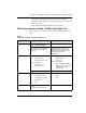
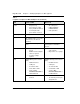
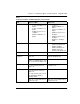
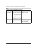
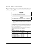
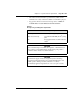
Table 9
Minimum fastener requirements
Type of wall Fasteners
Wooden studs #10 wood screws Embedded a minimum of 1
in. in wood studs
Metal studs # 14 sheet metal
screws
Embedded a minimum of 1
in. in metal studs
Concrete
(2000 PSI)
1/4 in. HILTI KB-II Embedded a minimum of
1 1/8 in.
Masonry 1/4 in. Ramset
Redhead Dynabolt
sleeve anchor
WARNING
Failure to follow grounding recommendations can result in a system
installation that is:
• unsafe for personnel working on, or using the equipment
• not protected correctly from lightning or power transients
• subject to service interruptions