
User's Manual

Page 34 of 332 Chapter 2 — Identifying the Option 11C Mini equipment
553-3021-209 Standard 3.00 April 2000
Note:
Set the dip switches before the system powers up.
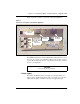
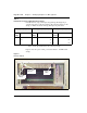
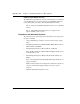
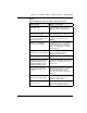
Figure 5 shows the power switch, power status indicator, and DIP switch
settings.
Figure 5
Front of chassis
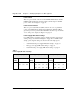
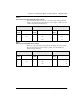
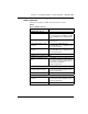
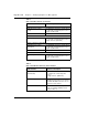
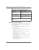
Table 4
North American power supply DIP switch settings
In North America, usage of the high voltage Message Waiting Lamp is
optional and requires -150V when enabled. The following table shows the
settings for 20Hz, 86V and the Message Waiting Lamp is disabled.
Ringing Frequency (Hz) Ringing Amplitude (Vrms) Message Waiting Lamp (VDC)
Switch
Setting
20 25 50
Switch
Setting
70 75 80 86
Switch
Setting
-120 -150 Disable
1 ON 3 ON 6 NOT USED
2 ON 4 ON 7 ON
5 ON 8 ON
Power status
indicator
DIP switch
Power
switch
settings