
User's Manual


Chapter 2 — Identifying the Option 11C Mini equipment Page 29 of 332
Option 11C Mini Planning and Installation Guide
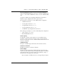
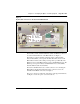
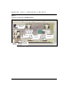
Figure 2
25-pair cable connectors on the back of the Main Chassis
The Auxiliary (AUX), Serial Data Interface (SDI), and Ethernet connectors
are on the back left-hand side of the Main Chassis. See Figure 3.
The AUX port connects auxiliary equipment, such as a Power Failure
Transfer Unit (PFTU), to the Option 11C Mini. The SDI connector in the
Main Chassis interfaces three SDI ports using a three-port SDI cable. The
Ethernet connector in the Main Chassis provides a 10 Mbit Ethernet port. The
Ethernet port accepts an industry-standard Medium Access Unit (MAU).
Insert the Ethernet cable into this MAU.
The back of the Main Chassis also contains connectors for connecting the
Main Chassis and the Chassis Expander. These connectors are for the
DS-30X and CE-MUX connections. See Figure 3.
The power connector is at the back of the chassis on the upper left-hand side.
See Figure 3. Secure the power cord with a cable tie.
25-pair
connectors