
User's Manual

Chapter 18 — Connecting the trunks Page 261 of 332
Option 11C Mini Planning and Installation Guide
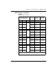
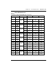
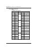
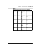
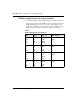
E&M TIE trunk card (4-Wire)
Table 62
E&M TIE trunk card (4-wire)
Cables Card 1 through
Card 10 from chassis
Column 1
Type 1 & 5
Column 2
Type 1 & 5
Pair Color Unit #
Pins Lead Designations
1T
1R
W-BL
BL-W
Unit
0
26
1
RA
RB
TA
TB
2T
2R
W-O
O-W
27
2
TA
TB
RA
RB
3T
3R
W-G
G-W
28
3
E
M
E
M
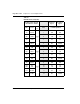
4T
4R
W-S
S-W
Unit
1
30
5
RA
RB
TA
TB
5T
5R
R-BL
BL-R
31
6
TA
TB
RA
RB
6T
6R
R-O
O-R
32
7
E
M
E
M
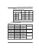
7T
7R
R-BR
BR-R
Unit
2
34
9
RA
RB
TA
TB
8T
8R
R-S
S-R
35
10
TA
TB
RA
RB
9T
9R
BK-BL
BL-BK
36
11
E
M
E
M
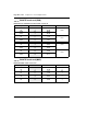
10T
10R
BK-G
G-BK
Unit
3
38
13
RA
RB
TA
TB
11T
11R
BK-BR-
BR-BK
39
14
TA
TB
RA
RB
12T
12R
BK-S
S-BK
40
15
E
M
E
M
Note:
The cable pair designated TA, TB is the transmit pair. The pair designated
RA, RB is the receive pair.