
User's Manual

Chapter 15 — Installing and connecting SDI and Ethernet ports Page 193 of 332
Option 11C Mini Planning and Installation Guide
Installing and connecting SDI ports
You can use a switch setting on the circuit card’s faceplate to control the baud
rate for port 0. Make sure the baud rate and device option settings are set
correctly.
Note:
When the time comes to configure ports 1 and 2, configure them
in Overlay 17.
• Use Port 0 for software installation and upgrades. SDI port 0 is the only
SDI port that you can use for software installation and upgrades.
• You can use all three ports on the MSC card to connect terminals or
modems.
• Use an NTBK48 3-port SDI cable with the MSC card.
Note:
The default baud rate of the MSC card is 1200 bps; the maximum
data rate is 19,200 bps. When you change the DIP switch on the
faceplate, make sure only one baud rate switch is set to ON. See
Table 38.
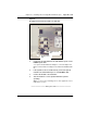
Procedure 24 describes how to connect a terminal, modems, and other
devices, such as CDR devices and additional TTYs, to the MSC card.
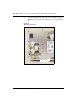
Procedure 24
Connecting SDI ports on the MSC card
1 The NTBK48 3-port SDI cable has one ferrite filter attached to it.
Connect an additional ferrite filter as close as possible to the
9-pin connector on the NTBK48 3-port SDI cable.
Note:
The additional ferrite filter comes with the Option 11C Mini
system.
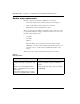
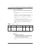
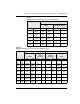
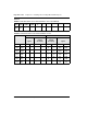
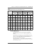
Table 38
Default port configuration for the MSC card
Port Use Baud rate Data bits Stop bits Parity
0 MTC/SCH/BUG Set by a DIP switch 8 1 None
1 MTC/SCH/BUG 1200 (See Note 1) 8 1 None
2 MTC/SCHBUG 1200 (See Note 2) 8 1 None