
User's Manual

Chapter 13 — Installing and connecting the cross-connect terminal Page 171 of 332
Option 11C Mini Planning and Installation Guide
• one 25-pair cable from each QUA6 PFTU
• wiring from telephones and trunks
Installing the BIX cross-connect terminal
Procedure 19 describes how to install the BIX cross-connect terminal.
Procedure 19
Installing the BIX cross-connect terminal
1 Refer to the equipment layout plan to determine where to place
the cross-connect terminal.
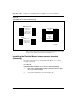
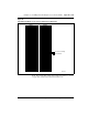
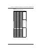
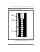
2 Layout the terminal blocks as shown in Figure 48 on page 172.
For information about the BIX system, refer to
BIX Installation and
Servicing (631-4511-200)
.
3 Attach labels on the cross-connect terminal to indicate the
terminal blocks assigned to the following:
• 25-pair cables from the chassis
• AUX wiring
• Power Failure Transfer Units (PFTUs)
• telephones and consoles
•trunks
• miscellaneous equipment
Note:
If you are installing the BIX cross-connect system, refer to
BIX
Installation and Servicing
(631-4511-200). This document
provides
information about labels used with the BIX terminal blocks.
—————————— End of Procedure ——————————
WARNING
Always use caution when installing or modifying telephone lines. Do
not install telephone wiring during a lightning storm. Never touch
uninsulated telephone wiring, unless the line is disconnected at the
network interface.