
User's Manual

Page 160 of 332 Chapter 12 — Installing the circuit cards
553-3021-209 Standard 3.00 April 2000
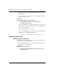
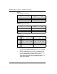
Table 30
Switch settings (Ports 0 and 1)
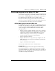
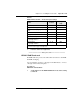
Table 31
Switch settings (Ports 2 and 3)
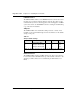
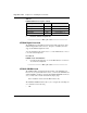
Table 32
Jumper settings
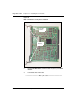
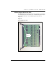
2 Insert the card in its assigned slot.
You can install the NTAK02 SDI/DCH card in slots 1 to 3 of the Main
Chassis.
3 Connect an NTAK19FB four port cable (or an NE-A25-B cable)
from the corresponding connector at the back of the chassis. If
you use an NE-A25-B cable, terminate this cable at the
cross-connect terminal. Because the NTAK19FB cable is
equipped with connectors, it does not require termination at the
cross-connect terminal.
Port
0
Port
1
SW
1-1
SW
1-2
SDI DCH OFF OFF
SDI DPNSS OFF ON
— ESDI ON ON
Port
2
Port
3
SW
1-3
SW
1-4
SDI DCH OFF OFF
SDI DPNSS OFF ON
— ESDI ON ON
Port
Jumper
location
Strap
for DTE
Strap
for DCE
Jumper
location
RS422 RS232
Port 0 J10 C - B B - A
Port 1 J7
J6
C - B
C - B
B - A
B - A
J9
J8
C - B
C - B
B - A
B - A
Port 2 J5 C - B B - A
Port 3 J4
J3
C - B
C - B
B - A
B - A
J2
J1
C - B
C - B
B - A
B - A