
Server User Manual

Page 442 of 488 Installing and cross-connecting a Power Fail Transfer Unit
553-3041-210 Standard 4.00 September 2007
The following procedures are provided in this chapter:
1 Procedure 115: "Installing and connecting a QUA6 PFTU" on page 442
2 Procedure 116: "Connecting an analog (500/2500-type) telephone to a
PFTU" on page 450
3 Procedure 117: "Connecting a Trunk to a PFTU" on page 452
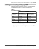
Installing and connecting a QUA6 PFTU
Follow Procedure 115 to install and connect a QUA6 PFTU. Refer to the
equipment layout plan for the location of the PFTU.
Note: The QUA6 PFTU operates with loop-start and ground-start
Central Office trunks. With ground start trunks, the associated telephone
set must have a ground start button.
Procedure 115
Installing and connecting a QUA6 PFTU
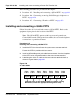
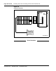
1 Install the PFTU on the wall near the system cross-connect terminal.
Fasten the PFTU in position with four screws.
2 Install an NE-A25B-type 25-pair cable from connector J1 on the faceplate
of the PFTU to its assigned location at the cross-connect terminal.
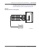
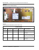
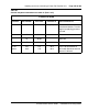
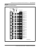
3 Label the pairs of the J1 cable on the cross-connect terminal block as
shown in Figure 150 on page 442.
Figure 150
J1 cable labels
Control PFT1 PFT2 PFT3 PFT4 PFT5
PFT1
Power
Pairs
1 to 4
Pairs
1 to 4
Pairs
1 to 4
Pairs
1 to 4
Pairs
1 to 4
Pairs
1 to 4
Pairs
1 to 4
Label the pairs on the terminal block as shown. If using
BIX blocks, attach the appropriate designation strip.