
Server User Manual

Page 228 of 488 Configuring a Small System Controller
553-3041-210 Standard 4.00 September 2007
a. Attach the appropriate port number label “2” or “4” to the respective
cable.
b. Install these cables firmly into the RJ-45 ports on the 100BaseT
daughterboard (dual port) #2. Completely insert each cable. See
Figure 82 on page 230 and Figure 83 on page 231.
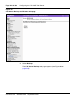
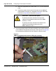
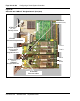
3 Insert the red black yellow LED cable on the SSC into the LED connector
on the 100BaseT daughterboard (dual port). See Figure 81 on page 228.
This connection provides the link status display on the front cover.
Figure 81
100Baset daughterboard (dual port) LED cable connector
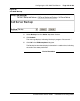
CAUTION — Service Interruption
The RJ-45 connectors located on the top of the
100BaseT daughterboard (dual port) are for Media
Gateways 1 and 3.
The RJ-45 connectors located on the bottom of the
100BaseT daughterboard (dual port) are for
Media Gateways 2 and 4.