
Server User Manual

Installing and configuring the Signaling Server software Page 189 of 488
Communication Server 1000E Installation and Configuration
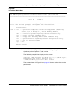
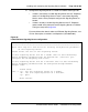
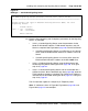
Figure 67
NRS type — stand-alone Signaling Server
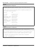
13 Enter the data networking and IP telephony parameters for the Signaling
Server, as prompted.
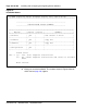
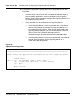
• If this is a Leader Signaling Server, enter the parameters for the
Node, ELAN network interface, TLAN network interface, and Call
Server as required. See Figure 68 on page 190. For the Call Server:
— If installing the Signaling Server at an office that is not a branch
office, enter the ELAN network interface IP address of the Call
Server.
— If installing the Signaling Server at a branch office, enter the
ELAN network interface IP address of the MG 1000B Core.
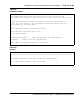
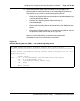
• If this is a Follower Signaling Server, enter the Hostname of the
Leader Signaling Server. See Figure 69 on page 190. Then go to
step 15 on page 192.
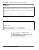
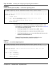
• If this is a stand-alone Signaling Server and not associated with a
Call Server (that is, b was selected in step 10 on page 186), enter the
TLAN subnet parameters as required. The Call Server IP address is
automatically set to 0.0.0.0. See Figure 70 on page 191. Then go to
step 14 on page 191.
The IP information applies to a temporary IP Telephony node.
Note: IP addresses shown in Figure 68, Figure 69 on page 190, and
Figure 70 on page 191 are examples.
CS 1000 Signaling Server Software Install Tool (sse-x.xx.xx)
=====================================================================
Please select the type of Network Routing Service (NRS) for this
Signaling Server.
Please enter:
<CR> -> <a> - Primary.
<b> - Alternate.
Enter Choice>