
Server User Manual


Page 158 of 488 Connecting MG 1000T system components
553-3041-210 Standard 4.00 September 2007
Procedure 34
Connecting the MG 1000T Core to an MG 1000T Expansion
1 Choose one of the following:
a. For point-to-point 100BaseT connectivity, go to step 2.
b. For 100BaseT connectivity over a distributed Campus Data Network,
go to step 9 on page 159.
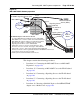
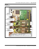
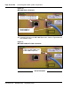
2 For the MG 1000T Core connect port 1 of the SSC 100BaseT
daughterboard #1 to the bulkhead connector #1 shown in Figure 39 on
page 159.
Note 1: If the SSC cable is connected to bulkhead Port 1, then use Port 1
on the back of the Media Gateway. If the SSC cable is connected to
bulkhead Port 2, then use Port 2 on the back of the Media Gateway.
Note 2: Port 1 on the MG 1000T Core must go to MG 1000T
Expansion 1, Port 2 to MG 1000T Expansion 2, and so on.
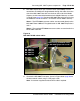
3 Connect the 100BaseT RJ-45 connector 1 on the back of the Media
Gateway to the identical connector on the first Survivable MG 1000T
Expansion, shown in Figure 40 on page 160.
Use the supplied NTTK34AA two-meter UTP CAT5 RJ-45 cross-over
cable to connect the MG 1000T Core and the Survivable MG 1000T
Expansion.
4 Connect port 1 of the MG 1000T Expansion 100BaseT daughterboard #2
to the bulkhead connector #1, as shown in Figure 39 on page 159.
5 For MG 1000T Expansion 2, connect port 2 of the MG 1000T Core
100BaseT daughterboard #1 to the bulkhead connector #2, shown in
Figure 39 on page 159
6 Connect the 100BaseT RJ-45 connector 2 on the back of the Media
Gateway to the 100BaseT RJ-45 connector 1 on the second MG 1000T
Expansion, shown in Figure 40 on page 160.
7 Connect port 1 of the MG 1000T Expansion 100BaseT daughterboard #2
to the bulkhead connector #1, as shown in Figure 39 on page 159