
Server User Manual


Page 104 of 488 Connecting CS 1000E system components
553-3041-210 Standard 4.00 September 2007
This chapter contains the following procedures:
• Procedure 12: "Connecting co-located Call Servers" on page 105
• Procedure 13: "Connecting Campus Redundant Call Servers"
on page 106
• Procedure 14: "Connecting the CS 1000E Core Call Servers to an
MG 1000E" on page 107
• Procedure 16: "Connecting a Signaling Server to the ELAN"
on page 111
• Procedure 17: "Connecting a Signaling Server to the TLAN subnet"
on page 112
• Procedure 18: "Inserting a Shielded 50-pin to Serial/ELAN/TLAN
adapter on to a Media Card" on page 113
• Procedure 19: "Connecting a Media Card to the ELAN subnet"
on page 114
• Procedure 20: "Connecting a Media Card to the TLAN subnet"
on page 115
• Procedure 21: "Connecting a Media Gateway to a Media Gateway
Expansion" on page 116.
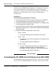
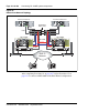
Connecting Call Server 0 to Call Server 1
The CS 1000E redundant architecture allows for the separation of
Call Server 0 and Call Server 1. The two processors are connected by either
a direct 100BaseT crossover cable or a carefully engineered Layer 2/VLAN
infrastructure.
Campus Redundancy provides the ability to separate the CS 1000E Call
Servers in a campus environment for “campus mirroring”. This feature
enables two Call Servers, one active and one redundant, to be connected
through an Ethernet network interface. Campus Redundancy can operate
using any vendor’s Layer 2 switching products, in addition to the
BayStack 470. The distance depends upon network parameter limitations
specified in Communication Server 1000: System Redundancy
(553-3001-307).