
Owner's manual


Configuring the QSDI card 991
Address switch settings
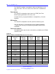
Table 416 "QSDI card address switch settings" (page 991) lists the
address switch settings for the QPC841 Quad Serial Data Interface card.
The address select jumpers and logic on the card address the UARTs
using two pairs of addresses: 0 and 1, 2 and 3, through 15 and 16. The
pairs do not need to be consecutive. Switch SW14 is used to select the
addresses for ports 1 and 2. Switch SW15 is used to select the addresses
for ports 3 and 4.
Table 416
QSDI card address switch settings
SW14
Port 1 Port 2
Switch settings
SW15
Port 3 Port 4 1234
5
6
7
8
01
off off off off off
on on on
23
off off off off off
on on
off
4
5
off off off off off
on
off
on
6
7
off off off off off
on
off off
89
off off off off off off
on on
10 11
off off off off off off
on
off
12 13
off off off off off off off
on
Device
pair
addresses
14 15
off off off off off off off off
Note 1: On SW16, positions 1, 2, 3, and 4 must be OFF.
Note 2: To avoid address conflicts, SW14 and SW15 can never use identical settings.
Note 3: To disable ports 1 and 2, set SW14 position 1 to ON. To disable ports 3 and 4, set SW15
position 1 to ON.
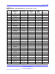
Baud rate switch settings
Table 417 "QSDI card baud rate switch settings" (page 991) lists the
switch settings necessary to set the baud rate.
Table 417
QSDI card baud rate switch settings
Port 1 – SW10 Port 2 – SW11 Port 3 – SW12 Port 4 – SW13
Baud
rate
1234123412341234
150
off off
on on
off off
on on
off off
on on
off off
on on
300
off
on
off
on
off
on
off
on
off
on
off
on
off
on
off
on
600
off off off
on
off off off
on
off off off
on
off off off
on
1200
off
on on
off off
on on
off off
on on
off off
on on
off
2400
off off
on
off off off
on
off off off
on
off off off
on
off
Nortel Communication Server 1000
Circuit Card Reference
NN43001-311 02.06 Standard
27 August 2008
Copyright © 2003-2008 Nortel Networks
.