
Owner's manual

990 QPC841 Quad Serial Data Interface card
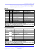
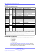
Table 415
Connector J2 pin assignments (cont’d.)
Pin
Number Port Signal Purpose in DTE mode Purpose in DCE mode
20
DTR Data terminal ready Data terminal ready (Note 2))
9
TD Transmitted data Transmitted data
10
RD Received data Received data
11
RTS Request to send (not
used)
Request to send (Note 2))
12 3
CTS Clear to send (Note 1) Clear to send
13
DSR Data set ready (Note 1) Data set ready
25
GND Ground Ground
24
CD Carrier detect (Note 1) Carrier detect (not used)
23
DTR Data terminal ready Data terminal ready (Note 2))
14
TD Transmitted data Transmitted data
15
RD Received data Received data
16
RTS Request to send (not
used)
Request to send (Note 2))
17 4
CTS Clear to send (Note 1) Clear to send
18
DSR Data set ready (Note 1) Data set ready
19
GND Ground Ground
21
CD Carrier detect (Note 1 Carrier detect (not used)
22
DTR Data terminal ready Data terminal ready (Note 2))
Note 1: In DTE mode, the signals CD, DSR, and CTS are tied to +12 volts (through a resistor) to
indicate that the QSDI port is always ready to transmit and receive data.
Note 2: In DCE mode, the signals DTR and RTS are tied to +12 volts (through a resistor) to indicate
that the QSDI port is always ready to transmit and receive data.
Configuring the QSDI card
Configuring the QSDI card consists of setting these option switches for
each serial port:
• Port address
• Baud rate
• DTE/DCE mode
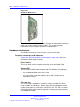
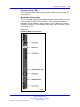
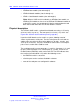
Figure 286 "QSDI card option switch locations" (page 993) shows the
location of the option switches on the QSDI card. Instructions for setting
these switches are in the section that follows.
Nortel Communication Server 1000
Circuit Card Reference
NN43001-311 02.06 Standard
27 August 2008
Copyright © 2003-2008 Nortel Networks
.