
Owner's manual


972 NTRB21 DTI/PRI/DCH TMDI card
combinations each for Mu255 to Mu255, Mu255 to A-Law, A-Law to
Mu255, and A-Law to A-Law. These values are selected to meet the EIA
loss and level plan.
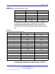
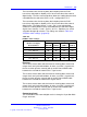
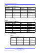
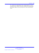
Table 408
Digital pad values and offset allocations
Offset
PAD set 0 PAD set 1
0
0dB –7db
1
2dB –8db
2
3dB –9db
3
4dB –10db
4
5dB 0.6db
5
6.1dB 7db
6
8dB 9db
7
–1dB 10db
8
–3dB 11db
9
–4dB 12db
A idle code, 7F 3db
B unassigned code, FF 14db
C 1dB
spare
D –2dB
spare
E –5db
spare
F –6db
spare
D-channel interface
The D-channel interface is a 64 kbps, full-duplex, serial bit-stream
configured as a Data Circuit-terminating Equipment (DCE) device. The
data signals include:
• receive data output
• transmit data input
• receive clock output
• transmit clock output
The bit rate of the receive and transmit clocks can vary slightly from each
other. This is determined by the transmit and receive carrier clocks.
Feature selection through software configuration for the D-channel
includes:
Nortel Communication Server 1000
Circuit Card Reference
NN43001-311 02.06 Standard
27 August 2008
Copyright © 2003-2008 Nortel Networks
.