
Owner's manual


88 Option settings
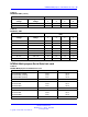
Application
Ringing
frequency
Ringing
voltage Jumper locations Ringing output
message waiting
British Telecom 25 Hz 80 V ac
P4
No high voltage
message waiting
Low impedance
Table 22
NT6D42 jumper locations P4 and P5
High voltage message waiting Pin location
Disable Jumper in P4
Enable Jumper in P5
Note: One jumper must be installed.
Table 23
NT6D42 jumper location J7
Ringing output Jumper location J7
Low impedance (normal) Connect pins 1 and 2
High impedance (Australia) Connect pins 2 and 3
Table 24
NT6D42 SW1
Ringing frequency (Hz)
Position SW1
20 1
25 2
50 3
Table 25
NT6D42CB SW2
SW2
Ringing
voltage
Message waiting
voltage 1 2 3 4
86 V ac –120 V dc off off off off
86 V ac –150 V dc off off off
on
80 V ac –120 V dc
on
off off off
80 V ac –150 V dc
on
off off
on
75 V ac –120 V dc off
on
off off
75 V ac –150 V dc off
on
off
on
Nortel Communication Server 1000
Circuit Card Reference
NN43001-311 02.06 Standard
27 August 2008
Copyright © 2003-2008 Nortel Networks
.