
Owner's manual


NT5D12 Dual DTI/PRI (DDP) card 85
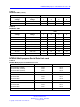
Table 19
DCH mode and address select switch settings (cont’d.)
Swit
ch
Description
S3 Switch Setting
5-7
For future use off
8
External DCH or Onboard DDCH
off - MSDL or DCHI card
on - Onboard DDCH
daughterboard
Table 20
NTBK51AA daughterboard address select switch settings
Device Address
1
Switch Setting
0
2
off off off off
1
on
off off off
2
off
on
off off
3
on on
off off
4
off off
on
off
5on
off
on
off
6
off
on on
off
7 ononon
off
8
off off off
on
9
on
off off
on
10
off
on
off
on
11
on on
off
on
12
off off
on on
13
on
off
on on
14
off
on on on
15
on on on on
Note 1: The maximum number of DCHI, MSDL, and DDCH devices in the system is 16.The
Device Addresses are equivalent to the MSDL DNUM designations. For programming information
on the MSDL, refer to technical document Software Input/Output Reference — Administration
(NN43001-611)guide.
Note 2: Device address 0 is commonly assigned to the System Monitor.
Illustrations of switch locations and settings
Figure 18 "Switch functions and areas" (page 86) displays functional areas
for switches on the NT5D12 DDP card.
Nortel Communication Server 1000
Circuit Card Reference
NN43001-311 02.06 Standard
27 August 2008
Copyright © 2003-2008 Nortel Networks
.