
Owner's manual

Physical description 779
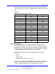
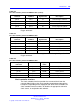
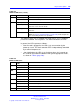
Table 329
NTAK10 LED states (cont’d.)
LED
State
Definition
LBK
On (Yellow) NTAK10 is in loop-back mode.
Off NTAK10 is not in loop-back mode.
CC
On (Red) The clock controller is switched on and disabled.
On (Green) The clock controller is switched on and is either locked to a
reference or is in free-run mode.
Flashing (Green) The clock controller is switched on and locking onto the primary
reference.
Off The clock controller is switched off.
Note: See “Clock controller interface” (page 793) in this chapter for
more on tracking and free-run operation.
The 2Mb DTI pack uses a standard IPE-sized (9.5" by 12.5"), multilayer
printed circuit board. The faceplate is 7/8" wide and contain six LEDs.
In general, the LEDs operate as follows:
• after the card is plugged in, the LEDs (a-e) are turned on by the
power-up circuit. The clock controller LED is independently controlled
by its own microprocessor
•
after initialization, the LEDs (a-e) flash three times (0.5 seconds on,
0.5 seconds off) and then individual LEDs go into appropriate states,
as shown in "Table" (page 780) .
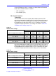
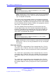
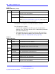
Table 330
NTAK10 LED states
LED
State
Definition
DIS
On (Red) The NTAK10 circuit card is disabled.
Off The NTAK10 is not in a disabled state.
OOS
On (Yellow) The NTAK10 is in an out of service state
Off The NTAK10 is not in an out of service state
NEA
On (Yellow) A near end alarm state has been detected
Off No near end alarm
FEA On (Yellow) A far end alarm state has been detected
Off No far end alarm
LBK
On (Yellow) NTAK10 is in loop-back mode
Off NTAK10 is not in loop-back mode
CC
On (Red) The clock controller is switched on and disabled
Nortel Communication Server 1000
Circuit Card Reference
NN43001-311 02.06 Standard
27 August 2008
Copyright © 2003-2008 Nortel Networks
.