
Owner's manual


NTAK02 SDI/DCH card 753
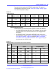
Two ports offer the option for DTE/DCE configuration. This option is
selected from a jumper on the card. Table 310 "Jumper settings" (page
753) shows the jumper settings.
Table 310
Jumper settings
Port Jumper location
Strap for
DTE
Strap for
DCE
Jumper
location RS422 RS232
0
J10 C - B B - A
1
J7 J6
C-BC
-B
B-AB
-A
J9 J8
C-BC
-B
B-AB
-A
2
J5 C - B B - A
3
J4 J3
C-BC
-B
B-AB
-A
J2 J1
C-BC
-B
B-AB
-A
Connecting to the ports
External devices are connected to the SDI/DCH card by the following:
• the NTAK19FB four-port SDI cable. This cable does not have to be
terminated at the cross connect terminal since it is equipped with
connectors.
•
the NE-A25-B cable. Terminate the NE-A25-B cable at the cross
connect terminal. Tables Table 311 "NTAK02 pinouts - Port 0 at the
cross-connect terminal" (page 753) through Table 314 "NTAK02
connections at the cross-connect terminal - Port 3" (page 755) give
the pinouts for the SDI/DCH card.
Table 311
NTAK02 pinouts - Port 0 at the cross-connect terminal
RS232
Cable
Signal
Designations
I=Input O=Output
Pair
Color
DTE
DCE
DTE
DCE
1T
1R
W-BL
BL-W
0
DTR
0
DCD
—
O
—
I
2T
2R
W-O
O-W
DSR
DCD
CH/CI
DTR
I
I
O
O
3T
3R
W-G
G-W
RTS
CTS
CTS
RTS
O
I
I
O
4T
4R
W-BR
BR-W
RX
TX
TX
RX
I
O
O
I
5T
5R
W-S
S-W
—
SG
—
SG
—
—
—
—
Nortel Communication Server 1000
Circuit Card Reference
NN43001-311 02.06 Standard
27 August 2008
Copyright © 2003-2008 Nortel Networks
.