
Owner's manual


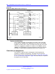


728 NT8D41BA Quad Serial Data Interface Paddle Board
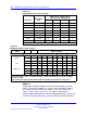
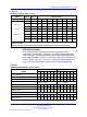
Table 289
NT8D41BA DTE/DCE/Fiber switch settings (cont’d.)
Port 1 — SW 3 Port 1 — SW 2
Mode 1 2 3 4 5 6 1 2 3 4 5 6
NT1P61 (Fiber)
on on on on on
off
on on on
off
on
off
Port 4 — SW 9 Port 4 — SW 8
DTE (terminal)
on on on
off
on
off off
on
off
on
off
on
DCE (modem) off off off
on
off
on on
off
on
off
on
off
NT1P61 (Fiber)
on on on on on
off
on on on
off
on
off
Software service changes
Once the NT8D841BA QSDI paddle board has been installed in the
system, the system software needs to be configured to recognize it, using
the Configuration Record program LD 17. Instructions for running this
program are found in
Software Input/Output Reference — Administration
(NN43001-611).
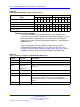
Some of the prompts that are commonly used when running the
Configuration Record program LD 17 are shown in Table 290 "LD 17 -
Prompts to configure the NT8D841Ba paddle board." (page 728) These
parameters must be set for each port if both ports are being used.
Table 290
LD 17 - Prompts to configure the NT8D841Ba paddle board.
Prompt Response Description
REQ: CHG Change configuration
TYPE: ADAN Configuration type
ADAN
NEW TTY x
NEW PRT x
Define a new system terminal (printer) port as device x, where
x = 0 to 15.
CTYPE SDI4 Quad port card
DES XQSDI Quad density QSDI paddle board.
USER
xxx
Enter the user of port x. The values that can be entered
depend on the software being used. See the Software
Input/Output Reference — Administration (NN43001-611) for
details.
XSM (NO) YES Port is used for the system monitor.
Nortel Communication Server 1000
Circuit Card Reference
NN43001-311 02.06 Standard
27 August 2008
Copyright © 2003-2008 Nortel Networks
.