
Owner's manual


Applications 713
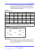
See Table 281 "Pad switching algorithm" (page 711) for the pad switching
control for the various through connections and the actual port-to-port
loss introduced for connections between the E and M Trunk card and any
other IPE port designated as Port B. Figure 242 "Pad orientation" (page
713) shows the pad switching orientation.
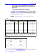
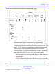
Table 282
Pad switching algorithm
Port B pads E and M Trunk Pads Port-to-port loss (dB)
Port B
Transmit
DtoA
Receive
AtoD
Transmit
DtoA
Receive
AtoD
Port B to
E and M
E and M to
Port B
IPE line N/A N/A Out In
2.5 3.5
Universal
trunk (TRC)
Out Out In In
00
IPE tie (VNL) In Out In Out
00
PE line N/A N/A Out In
3.0 4.0
PE CO/FX/W
ATS (TRC)
Out Out In In
00
PE tie Out Out In In
00
Note: Transmit and receive designations are from and to the CS 1000. Transmit is from the CS
1000 to the external facility (digital-to-analog direction in the E and M Trunk card). Receive is to the
CS 1000 from the external facility (analog-to-digital direction in the E and M Trunk card).
Figure 242
Pad orientation
Applications
The optional applications, features and signaling arrangements for each
trunk are assigned through unique route and trunk data blocks. Refer to
Features and Services (NN43001-106-B) for information about assigning
features and services to trunks.
Nortel Communication Server 1000
Circuit Card Reference
NN43001-311 02.06 Standard
27 August 2008
Copyright © 2003-2008 Nortel Networks
.