
Owner's manual


Configuration 711
• TRC for a 2-wire non-VNL trunk facility with a loss of greater than 2
dB, or for which impedance compensation is provided, or for a 4-wire
non-VNL facility
•
NTC for a 2-wire, non-VNL trunk facility with a loss of less than 2 dB,
or when impedance compensation is not provided
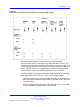
See Table 281 "Pad switching algorithm" (page 711) for the pad switching
control for the various through connections and the actual port-to-port loss
introduced for connections between the E and M Trunk card and any other
IPE or PE port designated as Port B.
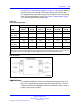
Figure 241 "Pad orientation" (page 711) shows the pad switching
orientation.
Table 281
Pad switching algorithm
Port B pads E and M Trunk Pads Port-to-port loss (dB)
Port B
Transmit
DtoA
Receive
AtoD
Transmit
DtoA
Receive
AtoD
Port B to
E and M
E and M to
Port B
IPE line N/A N/A Out In
2.5 3.5
Universal
trunk (TRC)
Out Out In In
00
IPE TIE
(VNL)
In Out In Out
00
PE line N/A N/A Out In
3.0 4.0
PE CO/FX/W
ATS (TRC)
Out Out In In
00
PE TIE Out Out In In
00
Note: Transmit and receive designations are from and to the Meridian 1. Transmit is from the
Meridian 1 to the external facility (digital-to-analog direction in the E and M Trunk card). Receive is
to the Meridian 1 from the external facility (analog-to-digital direction in the E and M Trunk card).
Figure 241
Pad orientation
Nortel Communication Server 1000
Circuit Card Reference
NN43001-311 02.06 Standard
27 August 2008
Copyright © 2003-2008 Nortel Networks
.